This Job Aid supports the NRTC Technician audience.
Understanding the NRTC Work Order
A Technician receives an email when a work order is set up and assigned to the Technician. This work order contains all of the information required to:
Complete Provisioning
Configure an email client
Demonstrate the web-based email
Demonstrate the Subscriber portal
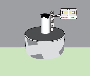
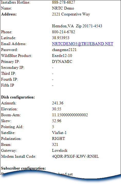
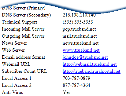
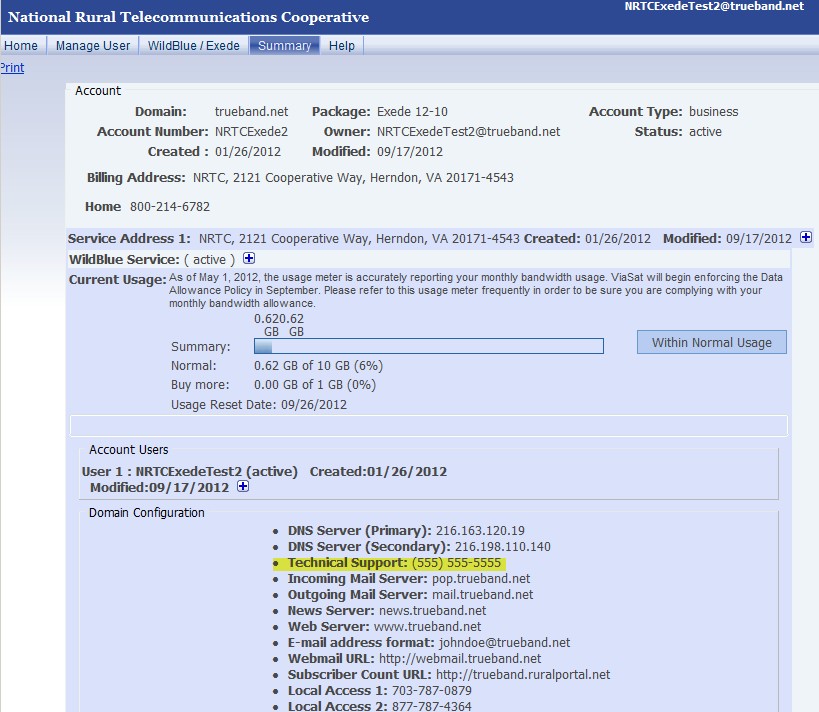
The list below provides a definition for each of the numbered fields in the image at the right.
Number
Definition
Email Address:
When used during Provisioning, this is the
Customer Code (SB2*) or the User Name (SB*).
When used during email setup, this is the primary
email account. It is created when the order is entered.
Password:
Used during SB Provisioning
Dish (Antenna) Configuration: Used to align the ODU equipment
APA: Used for SB/WildBlue ODU
Modem Key: Used for SB2/ViaSat ODU
All other fields: Used for all antennas
Important! The Boom-Arm setting listed is only valid for
SB/WildBlue ODUs. Technicians must manually calculate this
setting from the Elevation setting for other antennas.
SB2 = Elevation – 19.4 = Boom-Arm
Release Date: August 2018
SB = Elevation – 17.6 = Boom Arm
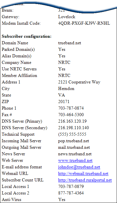
Domain Name: The member’s domain for:
AdminTool
Email addresses
Web-based email
Subscriber Portal
Technical Support:This phone number is for 24/7
Subscriber-facing Technical Support. Technicians provide this
number to the Subscriber before leaving the site.
Incoming Mail Server: This is the POP3 server that is used
when setting up an email client. In Outlook 2007, this information
is used in the Internet E-mail Settings dialog.
Outgoing Mail Server: This is the SMTP server that is used when
setting up an email client. In Outlook 2007, this information is used
in the Internet E-mail Settings dialog.
Email address format: This is the format the Subscriber uses to
create any additional email accounts. Recall, the primary email
address is already created using the same format.
Webmail URL: This is the website where Subscribers can
access their email, using a browser instead of an email client.
Subscriber Count URL: The URL for the Subscriber Portal.
This is where Subscribers can manage various types of
information related to their account, including email forwarding
if they do not wish to use their primary email account.
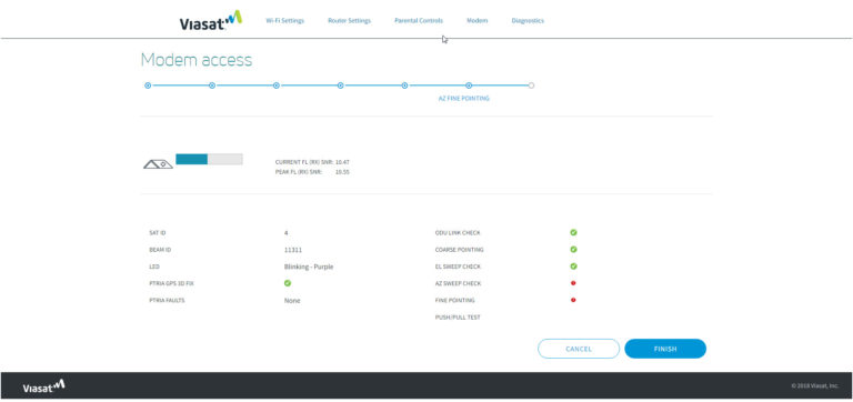
ViaSat-2/Viasat WiFi Gateway Point and Peak Job Aid
Coarse Point Azimuth with Wait Sequence Peak Elevation with Wait Sequence
Peak Azimuth Push/Pull Test Finishing Installation
This Job Aid supports all technician audiences. This process supports the VS1300 antenna and mounts. If using the SB2 or SB2+ modem, see ViaSat-1/SurfBeam 2 Point and Peak Job Aid.
Enter Installation Mode
Open the computer’s web browser and type this URL into the address bar:
http://192.168.100.1
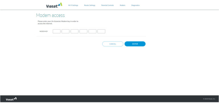
Click: Modem >> Install
The gateway enters the Modem Key Entry Mode.
Find the 24-digit Modem Key on the work order, and type it into the fields.
Click the Enter button in the lower right corner of the screen.
The system is now in Pointing and Peaking Mode.
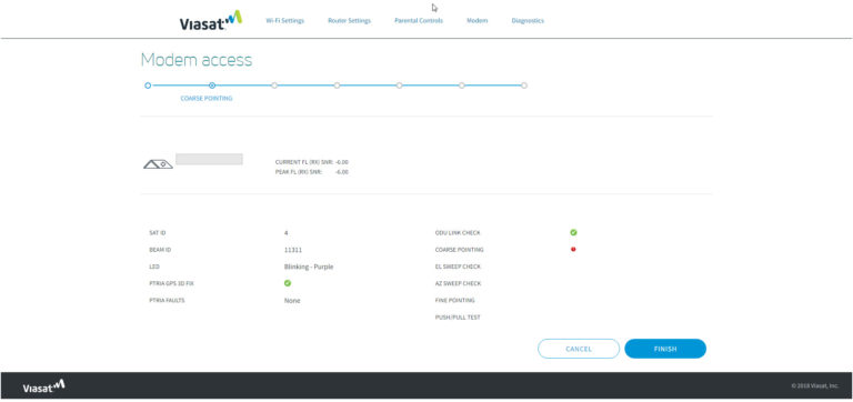
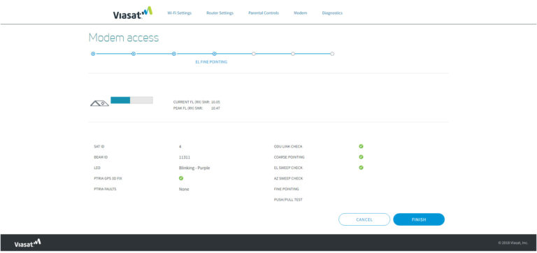
Confirm that the following are happening:
The gateway’s light is blinking a purple color
ODU Link Check indicator is green. If not, wait up to 4 minutes This confirms that the TRIA is connected to the gateway
The pTRIA is emitting the ‘heartbeat‘ tone
Click play to hear the “Heartbeat” tone.
The gateway and pTRIA are ready for the Point and Peak process.
TIP! Use the Status indicators (below the ODU Link Check) to guide your alignment process.
Release Date: October 2018
Sweep 1: Coarse Point Azimuth with Wait Sequence
Follow these steps to point the Azimuth.
From behind the antenna sweep the antenna to the right, about 10 degrees away from the line- of-sight selected during the Site Survey.
Sweep 1: Reverse the direction of the adjustment, listening for the pTRIA to emit the ‘ring ring’ tone.
Click play to hear the “Ring-Ring” tone.
Continue slowly sweeping the antenna toward the left, through several tones, until the pTRIA emits the ‘beep-beep’ tone. This indicates that you have exited the beam.
Click play to hear the “Beep-Beep” tone.
You have 15 seconds to start your next sweep and re-enter the beam or the gateway will reset. If the gateway resets, begin the process from the beginning.
Sweep 2: Reverse the direction of the adjustment, listening for the pTRIA to progress through the tone sequence. Stop the sweep when the pTRIA emits the ‘beep-beep’ tone. This is the end of the second learning pass.
Click play to hear the “Beep-Beep” tone.
Note: Use a slow, consistent tension on the antenna during this sweep. Not all of the tones may be heard.
Begin the third sweep within 15 seconds.
Sweep 3: Slowly sweep the antenna toward the center. Stop when the pTRIA emits the ‘high steady’ tone.
Click play to hear the “High Steady” tone.
Wait and listen for the pTRIA to emit the ‘wait’ tone. The antenna needs to be stationary while the ‘wait’ tone emits, in order to calibrate itself.
Click play to hear the “Wait” tone.
A green check mark should be populated next to “Coarse Pointing” indicating you have completed this step in the process.
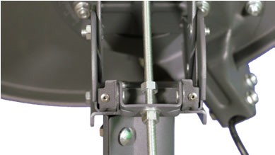
When the ‘high steady’ tone returns, finish this step by tightening the flange bolts, starting with the center flange bolt to maintain an even pressure on the tube canister.
Click play to hear the “High Steady” tone.
Peak Elevation with Wait Sequence
Follow these steps to complete the antenna elevation (fine) peaking process.
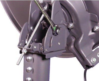
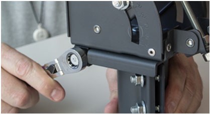
Slightly loosen the lockdown nuts in the arched slots on the sides of the elevation bracket. Next, turn the top 13mm nut on the elevation rod away from the top of the pivot casting.
Using the open wrench, adjust the lower nut on the elevation rod until the pTRIA lowers, and listen for the pTRIA to emit the ‘low/slow’ tone.
Click play to hear the “Low/Slow” tone.
This is the far edge of its frequency set. Stop, as this is the end of the first fine-tune learning pass.
Important: Do not pass the ‘low/slow’ tone when peaking the antenna.
Reverse the direction of the adjustment, and listen for the pTRIA to progress through the tone sequence. Be certain you hear the ‘high steady’ tone during this sweep and continue until you hear the ‘low-slow’ tone.
Stop the sweep when the pTRIA emits the ‘low/slow’ tone. This is the end of the second fine-tune learning pass.
Reverse the direction of the adjustment, and listen for the pTRIA to emit the ‘high steady’ tone. Wait and listen for the pTRIA to emit the ‘wait’ tone. The antenna needs to be stationary while the ‘wait’ tone emits.
Click play to hear the “High Steady” tone.
When high steady returns, add 1/8 turn to move the pTRIA slightly towards the center of the beam. Start by tightening the same nuts. Start with the elevation lock down bolts and then the top nut of the elevation rod.
A green check mark should be populated next to “EL Sweep Check,” indicating you have completed this step in the process.
Peak Azimuth
Follow these steps to complete the antenna Azimuth (fine) peaking process.
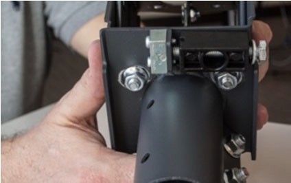
Loosen the Azimuth base plate bolts using a 13mm ratchet.
Using an open wrench, slowly turn the Azimuth fine-adjust bolt, listening for the pTRIA to emit the ‘low/slow’ tone. This means that the antenna has found the far edge of its frequency set.
Click play to hear the “Low/Slow” tone.
Stop, as this is the end of the first fine-tune learning pass.
Important: Do not pass the ‘low/slow’ tone when peaking the antenna.
Reverse the direction of the adjustment, and listen for the pTRIA to progress through the tone sequence.
Be certain you hear the ‘high steady’ tone during this adjustment and continue until you hear the ‘low-slow’ tone.
Stop the adjustment when the pTRIA emits the ‘low/slow’ tone. This is the end of the second fine- tune learning pass.
Reverse the direction of the adjustment again, now moving to the center, and listen for the pTRIA to emit the ‘final high steady’ tone. The antenna is now in the center of the beam.
Click play to hear the “Final High Steady” tone.
Note: The ‘final high steady’ tone is a higher pitched tone
Finish this step by tightening the Azimuth base plate bolts. A green check mark should be populated next to:
“AZ Sweep Check”
“Fine Pointing” This indicates you have completed this step in the process.
Note: The ‘final high steady’ tone may dip while tightening the base plate bolts. If the tone does not return to the ‘final high steady’ tone, then restart the pointing and peaking process from the beginning.
Push/Pull Test
Important: Before finishing the alignment, always perform a Push/Pull test
From behind the antenna, gently push and pull each side of the antenna
Gently push and pull the top of the antenna
The test passes when: every time pressure is added to the antenna, the pTRIA’s ‘final high steady’ tone dips and when the pressure is removed, the antenna returns to its ‘final high steady’ state.
Click play to hear the “Final High Steady” tone.
If the tone rises, the alignment is not correct. You must repeat the pointing and peaking process from the beginning.
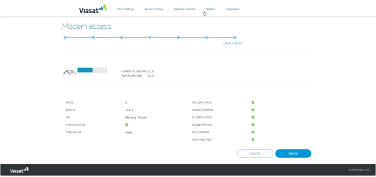
Finishing the Alignment
Once pointing and peaking are complete, the following steps are used to complete the alignment process and then provision (activate) the Viasat network.
Important: The modem’s Current SNR must be within .3 dB of the Peak SNR in order to pass QOI. If it is below this value, restart pointing and peaking from the beginning.
TIP! Notice that the indicators are all green, confirming that all steps are complete.
From the Modem GUI, click the Finish button. This will capture the results of the install process for reporting to the back office.
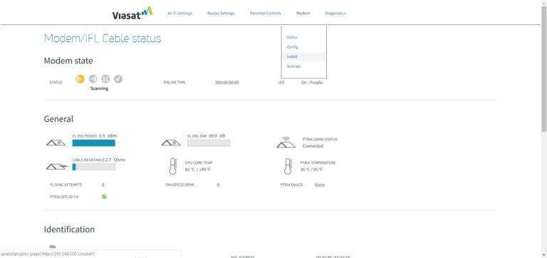
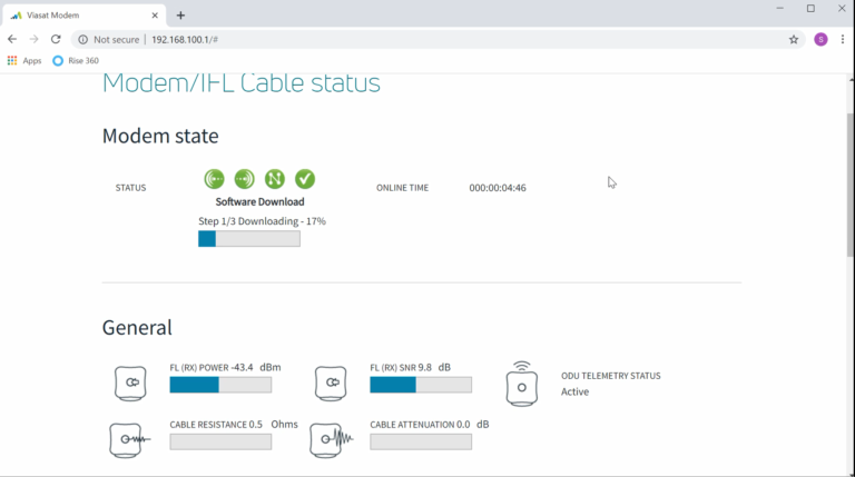
From the Modem/IFL Status page, watch for the gateway to go Online. Wait to see if a software download begins.
Important! Wait up to 10 minutes. Does a software download begin?
If yes, WAIT. The gateway is completing a required firmware upgrade. Do not interrupt the upgrade.
If no, continue to the next step.
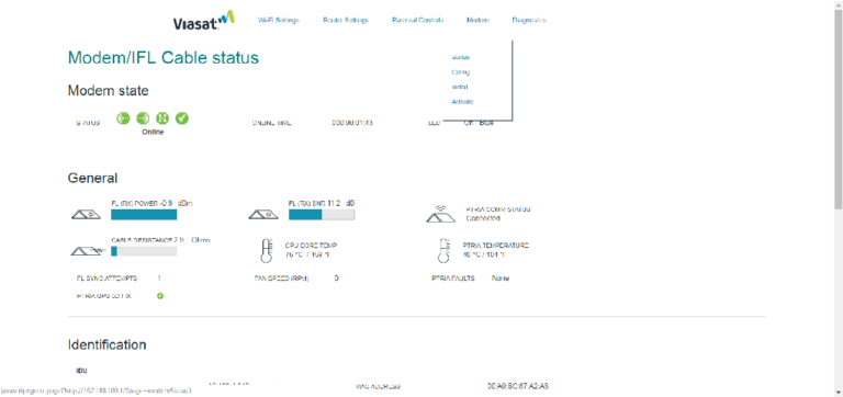
When the download is complete, the gateway will reboot. Wait for the status to show Online.
To begin Provisioning, click the Activate link on the top of the Modem/IFL Status page.
This Job Aid supports the NRTC Technician audience.
Subscriber Education Topics
After setting up the Subscriber’s email, it is time to introduce the service to the Subscriber. The information the Technician provides to the Subscriber varies depending on the requirements of the NRTC member provider.
Items that must be covered include the following:
Sign the Customer Agreement: Collect the signature as directed by the member
Demonstrate Surfing the Internet: Guide the Subscriber to the member Web site and add the link as a favorite or as their homepage
Demonstrate the Email Account: Send a test message to their new email account
Demonstrate Webmail for Remote Email Access: Guide the Subscriber to the URL provided on the work order and demonstrate how to send and retrieve email, manage contacts and use the calendar. Finish the demonstration by accessing the Help file.
Demonstrate the Subscriber Portal: Guide the Subscriber to the URL provided on the work order. Recommend that the Subscriber save the URL as a favorite. Demonstrate the various ways a Subscriber manages settings and monitor bandwidth usage. Finish the demonstration by accessing the Help file.
Provide the 24/7 Customer Technical Support Number: Review where the Customer can find the Technical Support number in the Subscriber Portal, and remind them that technical support for their service is available 24 hours a day/7 days a week.
Demonstrate Webmail for Remote Email Access
Every Subscriber has access to their email from any browser, using the webmail service provided with their account. To demonstrate this, ask the Subscriber to open their browser and navigate to the URL provided on the work order. Add the site as a bookmark/favorite in the browser and login to their webmail account, using the same email address and the Subscriber’s password used in the email client.
Demonstrate Subscriber Portal for Managing Settings
The Subscriber Portal is very similar to the AdminTool. The URL to access the portal is included on the work order. Have Subscribers add the Portal as a favorite before logging in. At the end of the demonstration, show them how to access the Help file. Follow these steps in the demonstration.
1.Go to the Subscriber Count URL shown on the work order.
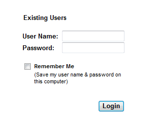
2. On the Login page, the User Name is the same Email address used in prior steps, and comes from the work order.
The Password is the Subscriber’s password given to the sales agent when the service was ordered.
Click Login to begin the demonstration.
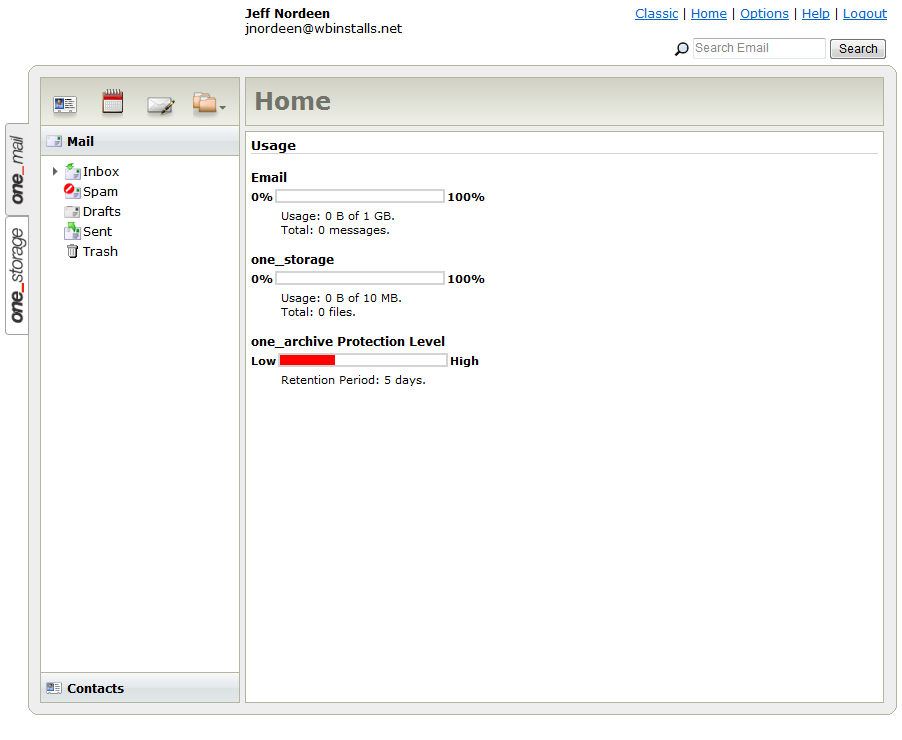
3. The Home tab appears; it is a synopsis of the Account’s domain, service, and subscriber information.
Click Manage User to continue the demonstration.
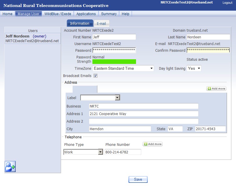
4.On the Manager User > Information sub-tab, the Subscriber can
update contact information
change password from the one created during the sales process Username and password are for
email/webmail
Subscriber portal
Click the Email sub- tab to continue the demonstration
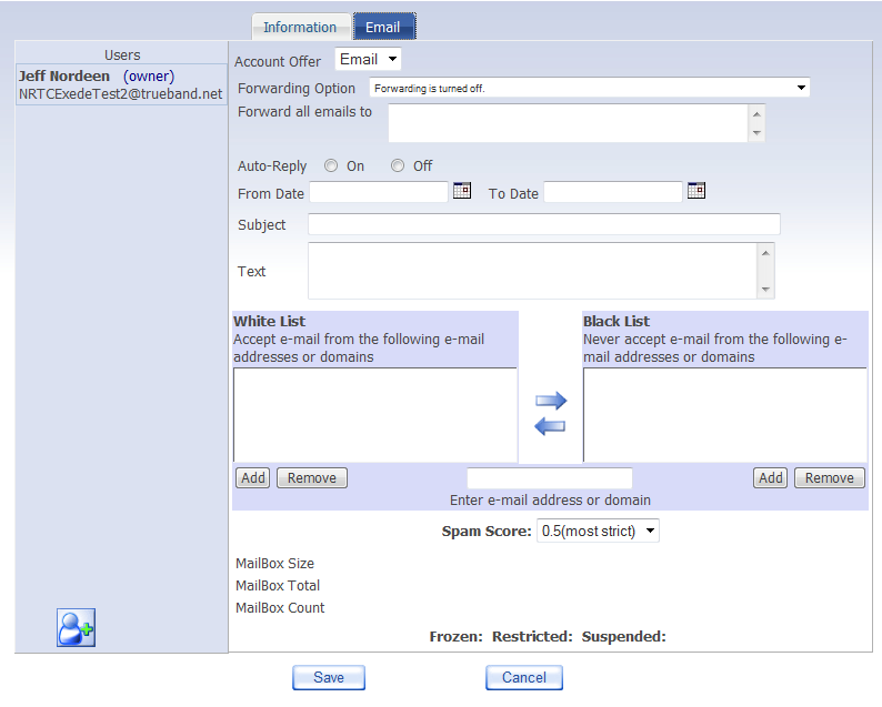
5.On the Manage User > Email sub-tab, the Subscriber can configure three options:
Email Forwarding
Auto-reply
Spam Blocking
Email Forwarding is necessary when the Subscriber does not wish to use this email account. The Forwarding Option down arrow displays the choices:
Forwarding is turned off
Forwarding is turned on, and no messages are stored in the user’s mailbox
Forwarding is turned on, and a copy of each message is stored in this user’s mailbox.
Click the WildBlue/Exede tab to continue the demonstration
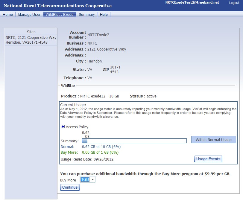
6.On the WildBlue/Exede tab, the subscriber can
Review service level and status information
Check Bandwidth monitor that shows data usage
Gain access to BuyMore ordering
Click the Summary tab to complete the demonstration.
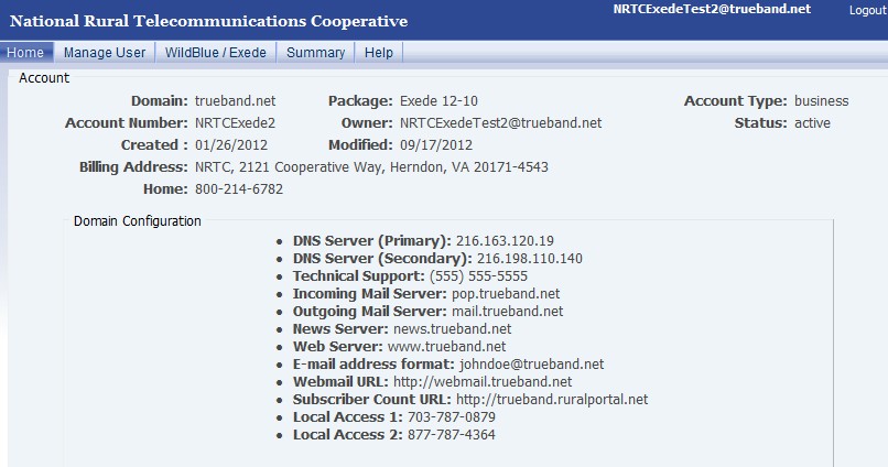
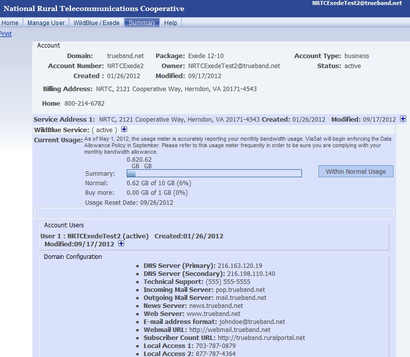
7.On the Summary tab, the Subscriber can find a one-stop for
Account info
Bandwidth monitor
Domain configuration
Contacting Technical Support
Remind the Subscriber that technical support is available 24 hours a day, seven days a week. Provide them with the number located on the work order and show them where that number is located on the Subscriber Portal Summary Tab.
This Job Aid supports the NRTC Technician audience.
Setting ‘Level 5’
Following the installation, provisioning, email set-up and education of the Subscriber, the final step is bringing the install to a Level Five (5) in the AdminTool. This process may be performed at the Subscriber’s location or at the member’s office, by either the Technician or a Customer Service Representative (CSR).
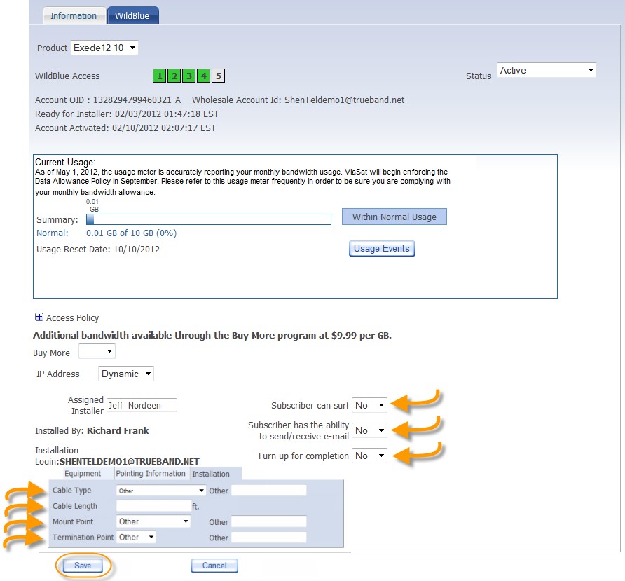
Follow these steps to set Level 5 in the AdminTool
1.After logging into the AdminTool and locating the work order, click the WildBlue tab.
2.Click the Installation tab at the bottom of the page.
3.Complete the fields using information from the installation.
4.Answer the three questions
in the top right corner with Yes
Subscriber can surf
Subscriber can send/receive email
Turn up for completion
5.Click Save, and confirm that WildBlue Access changes to Level 5.
This Job Aid supports the Global Business Services technican audience.
Surfaces
The only approved location for a telescoping pole mount is in firm ground, with no
danger from flooding. Telescoping pole mounts are for Community Wi-Fi and not residential applications.
Structural Elements
None
Important Considerations
The Telescoping Pole Mount installation requires additional materials not provided with the equipment
This installation type may also require building permits. Technicians are required to check the local building codes.
At minimum, the following requirements must be met for the telescoping pole mount:
Pole extends at least 12 inches below the ground surface, and is set in concrete
When fully extended, pole must be placed a minimum height of 15 above the ground
Other Considerations
The ground block must be within 10 feet of the NEC approved ground source
All antennas must be located at least 20 feet from any overhead power lines and 3 feet from any standard power circuit or electric light
DANGER! Always call your local safe dig number to locate power lines before you start the installation. These include overhead and underground power lines, electric lights, and power circuits.
Other Installation Resources
For complete assembly/installation instructions, please see manufacturers’ guides: Ruckus Zoneflex T300 Outdoor AP (US)
Dig the hole 8 inches in diameter (to fit the concrete form tube) and two feet deep, with straight sides
Ensure that hole is no greater than 10 feet from power source/pedestal
2. Concrete form tubes with a 8 inch inside diameter come in standard 4 foot sections
Cut concrete form tube down to 3 feet
Drill a 1 inch diameter hole at 12 inches from either side of the cut concrete form tube
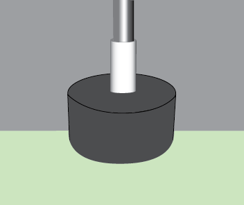
3. Place the 3 foot concrete form tube in the hole with 1 inch hole toward bottom. Tube will extend 12 inches above ground level
Re-pack dirt around the outside of the concrete form tube, so that any gaps between the form tube and the ground are filled, and the form tube is level, stable, and secure
4. Dig a 1 foot deep trench from form tube to power location “ensure cable locates completed”
Assemble 2 PVC pipe conduit sections as depicted
Insert 1 PVC pipe conduit section with straight shorter end protruding from form tube hole
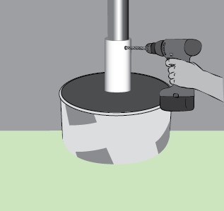
5. Remove black plastic sleeve from pole box, place duct tape over one sleeve end, drill hole 2 inches from bottom for ¼ inch x 6 inch bolt/anti-spin device
Insert ¼ inch x 6 inch bolt and secure ¼ inch nut and corresponding washer on each side
Tighten nuts until the anti-spin device is centered through the PVC pipe
6.Place 3 foot PVC pipe in center of concrete form tube
It will extend 18 inches above ground level (6 inches above the top of the form tube)
7. Secure black plastic sleeve and 1 PVC pipe conduit section by pouring at least 150 pounds of quick-setting concrete into the concrete form tube
8. Level black plastic sleeve while the concrete dries
Note: The black plastic sleeve must be completely level in order for the pole mount to be successful
9. Lay the telescoping pole along the ground and extend to height between 15 to 20 feet
Ensure that each section of the pole is firmly locked in place and does not spin or collapse back down
Note: Only the bottom section will be drilled for the anti-spin device
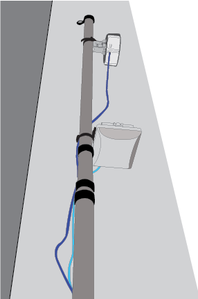
Mount the remote AP 3 to 6 inches from the top of the pole
Mount the remote SXT 2 to 4 feet from the top of the pole (ensure SXT will have line of sight to omnidirectional/sector antenna)
Note: Install the SXT oriented so that the CAT5 cable enters from the bottom
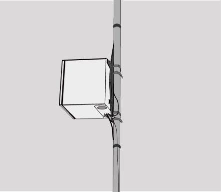
10. Mount the weatherproof (NEMA rated) enclosure a minimum of 7 feet above ground level, with 2 self-tapping screws
Use 2 U bolts. 1 on the top and 1 at the bottom
Unscrew right and left gland caps and glands, connect Ethernet cabling through holes, feed glands onto cables and reinsert glands
Screw gland caps back on.
Connect protruding Ethernet cables to SXT and AP.
Secure Ethernet cables to telescoping pole using cable ties & coil excess Ethernet cables and secure drip loop/s to pole.
11. Once the concrete is hard set:
Cut away the concrete form tube to ground level
Insert telescoping pole into black plastic sleeve until it is secure against the anti-spin device at the bottom of the sleeve
12. Ensure that the SXT faces the direction of the Base Station, for point-to-point signal
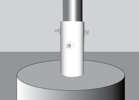
13. Mark black sleeve for 2 anti-spin devices:
At 90 degree angles from each other
One 2 inches from top of the sleeve
One 3 inches from top of the sleeve
Drill through both sides of sleeve and telescoping pole for ¼ inch x 6 inch bolts
14.Place ¼ inch x 6 inch bolts, washers, and nuts through holes Tighten ¼ inch nuts until telescoping pole is secure
15. Run power cable through conduit and into 1 foot trench
Run power cable along trench and through second PVC pipe conduit section, plug into local power, and fill trench.


 Summary