Quality Installation Standards (QIS)
Summary
Technicians are required to take photos after completing any installation or service calls.
This Job Aid provides photo requirement details needed for a residential installation to meet our quality installation standards.
Each work order must have all required photos uploaded within 72 hours of completion.
Table of Contents
Wall Mount | Roof Mount | Side “S” Mount | Low Profile “STUB” Mount | Brick Mount
Under Eave Mount | Non-Pen Mount | Rail Mount | Tile Roof Mount | Pole Mount
| Picture: Location |
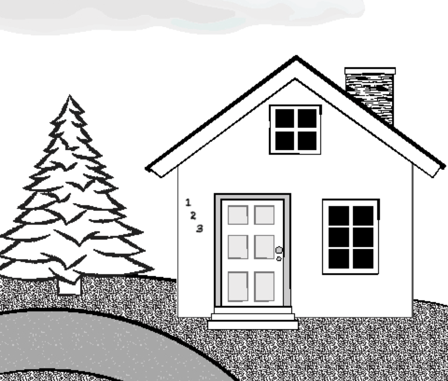
Take a picture showing a full frontal view of the home from the street:
- Do not take pictures of the customer, customer documents, or customer vehicle/license plate
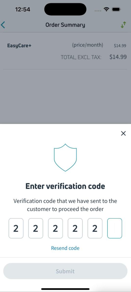
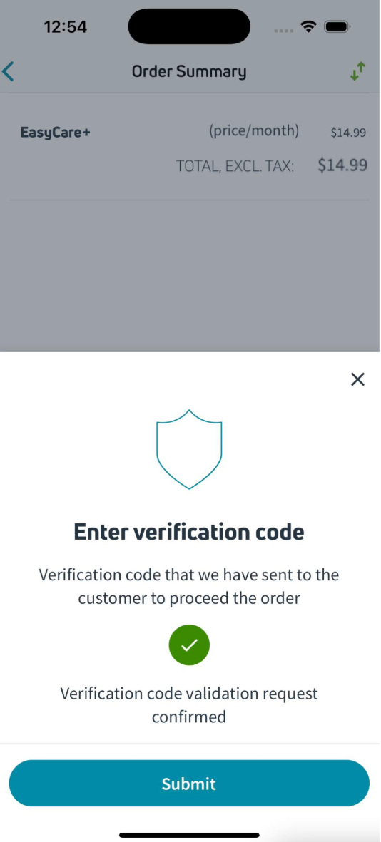
| Picture: Line of Sight |
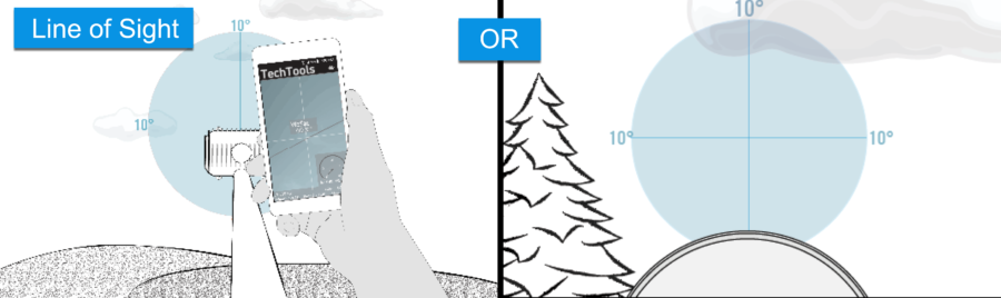
Take a picture showing a clear view of the southern sky toward the TRIA
- Take a picture that shows a clear line of sight.
- A picture can be taken from on top of the boom arm (where it connects to the reflector) toward the TRIA.
- OR a picture can be taken from behind the ODU.
Line of Sight should be:
- Clear in all directions by 10 degrees
- Clear of tree growth, seasonal foliage changes, and future development.
| Picture: Grounding |
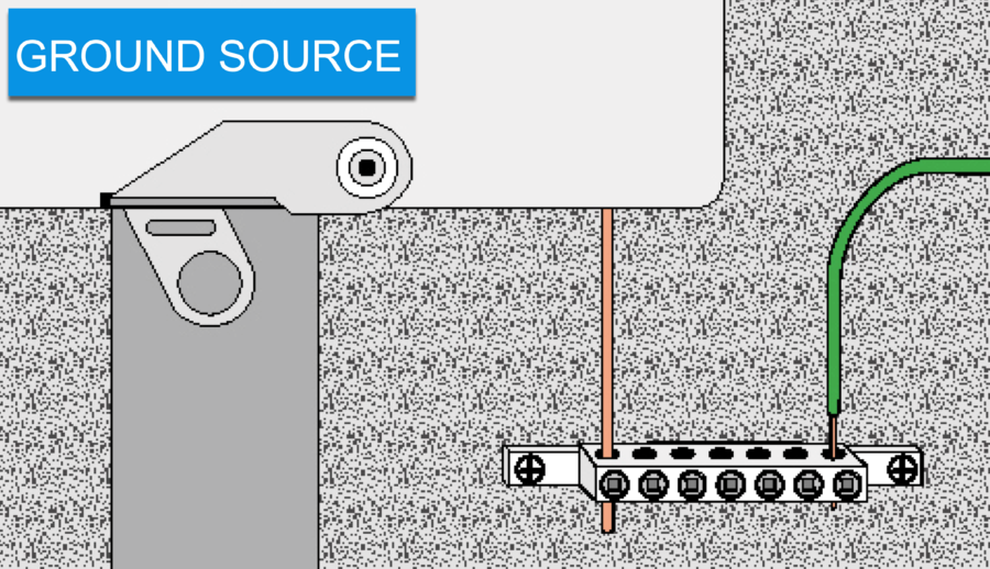
Take a picture of the ground source:
- show a UL-listed device attached to an NEC-approved ground source.
– IBT (required if present), #6 bare copper wire, back-bonded grounding electrode, metallic - raceway, meter box, grounded I-beam.
- Use matching metals (ex. copper to copper)
- Do not impede the opening of the meter box door.
- Do not share ground sources (Note: each IBT port is an available ground source)
- Scrape paint to allow metal-to-metal contact.
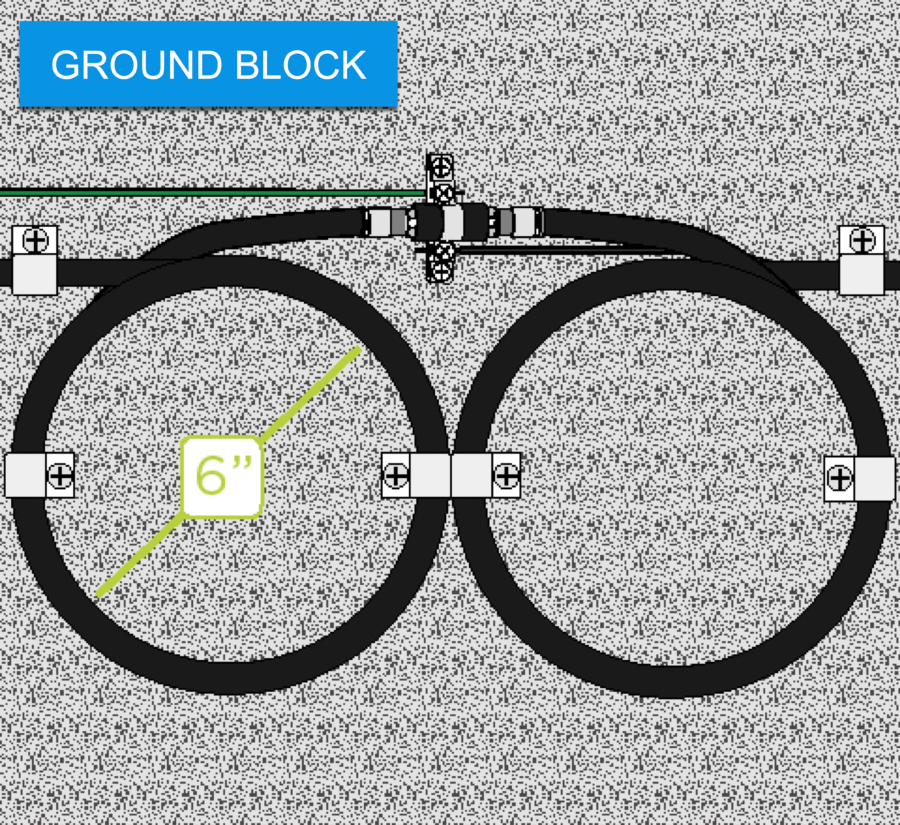
Take another picture of the ground block:
- Show the installation of a UL-listed, 3Ghz-rated ground block:
- Install compression connectors, and torque to 30 in. lbs.
- Use weather boots on both sides of the ground block.
- Form 6” diameter service loops.
- Attach ground block directly to structure (2 screws).
- Run the #10 gauge solid copper ground wire as straight and short as possible, with minimal bends (cannot exceed 20’).
- Connect messenger and ground wire to the ground block.
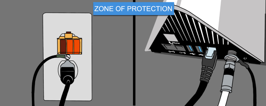
If using the Zone of Protection (ZOP), the antenna location must meet NEC ZOP requirements.
Take a picture showing:
- A properly secured bond to the electrical outlet wall plate.
- Use an adapter to convert the 3-prong grounded cord to a 2-prong cord.
- Outlet tester indicating properly wired circuit.
Take another picture of the properly attached nuts on both sides of the circle ring connector on the back of the modem.
| Picture: Cable |
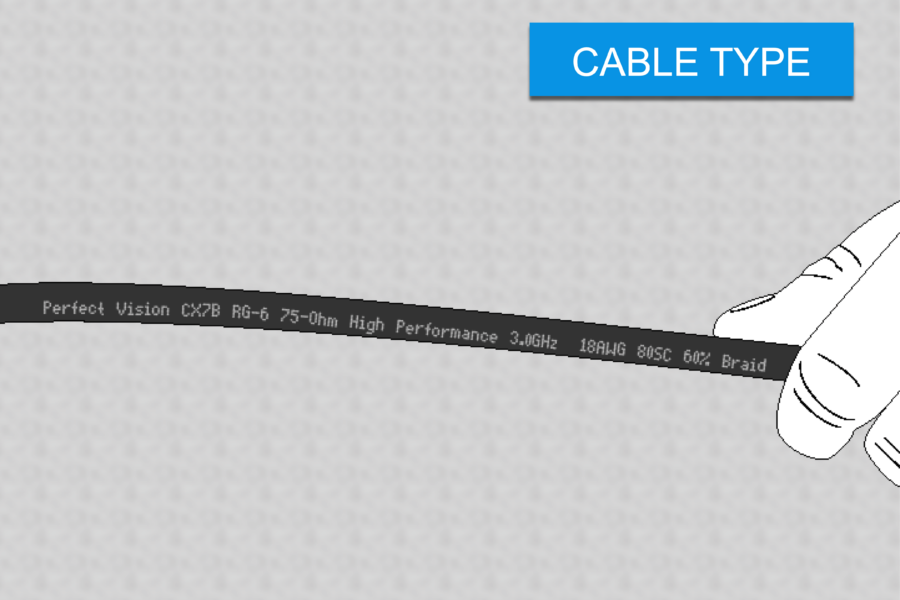
Take a picture showing a close-up of cable markings identifying:
- Cable type and model number.
- Solid copper, rated to 3GHz, 75 Ohm, 60% braid.
- The cable is in good condition.
- The cable type must be attached to the structure or mount.
- If more than one type is used (pre-wired structure), take a picture of both.
CABLING SPECS
- 150’ maximum run of RG-6 cable that is neat and follows the lines of the house.
- Attached using only approved screw clips.
- Continuous and does not use in-line barrels, excluding the ground block and wall plate.
- Never bent to 90-degree angles.
| Picture: Mount Type |
| Wall Mount |
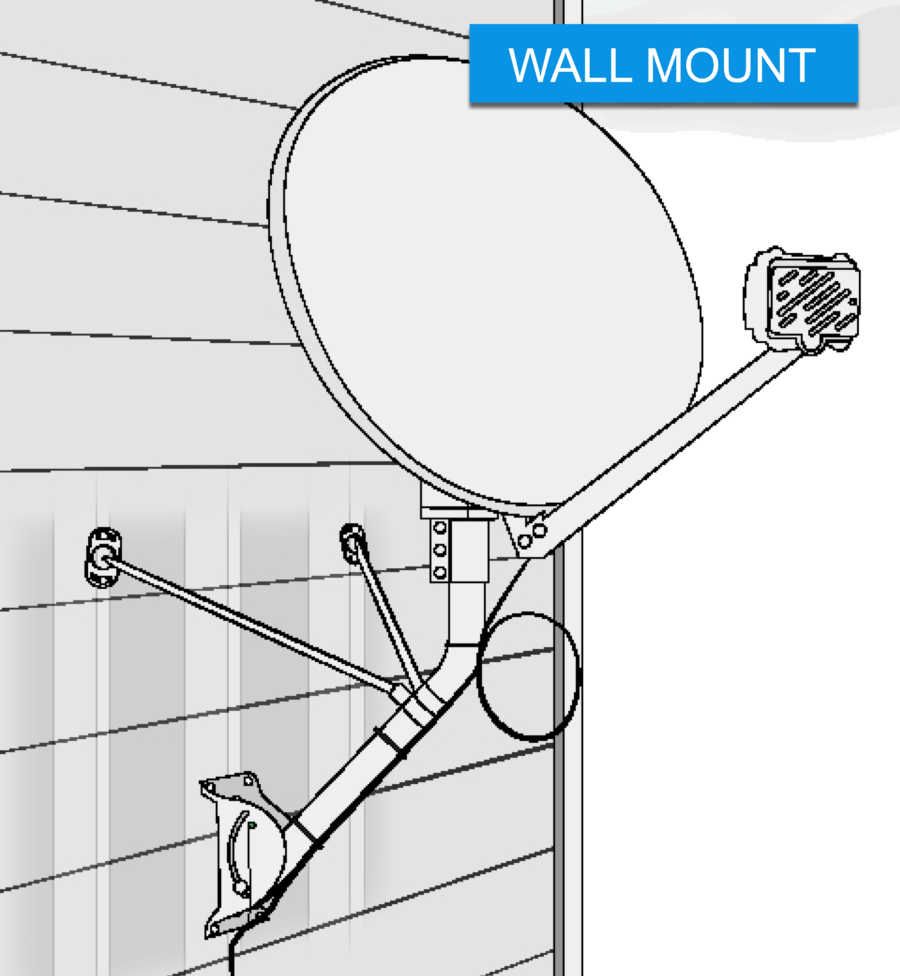
Take a picture showing a properly installed Wall Mount.
A properly installed Wall Mount picture includes:
- The attachment to an approved, structurally sound surface
- Mount antenna to not impede any high-traffic areas
- Position of monopoles
- Secured footplate and monopoles
- Zip-tie cable to the mast, including a service loop
Wall Mount specs:
- ODU is at least 3’ from the electrical panel and 20’ from the power lines
- Use only approved and matching ODU hardware
- Pre-drill holes required using a 1/4” wood bit
- Secure the footplate to the wall with:
- Two 3” lags through center holes into stud
- Four 2” lags through corner holes
- Position monopoles 2” below the bend, at an upward angle, forming a tripod
- Secure monopole plates to adjacent studs using two 3” lags
- Seal all drilled holes with silicone
- Zip-tie cable to the mast, including a 6″ diameter service loop
- Connect the messenger/ground wire to a green ground screw on the footplate
- Tighten all hardware completely
| Roof Mount |
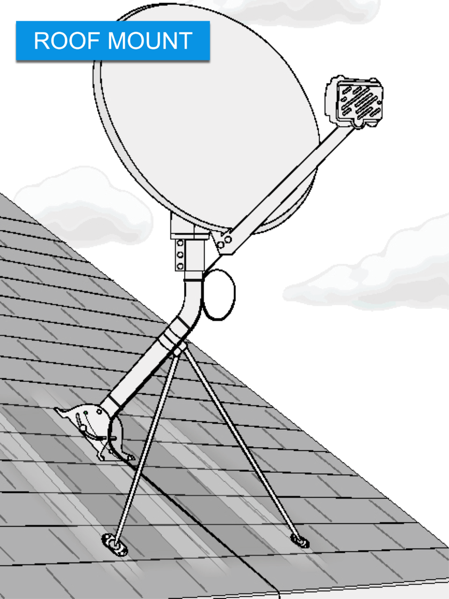
Take a picture showing a properly installed Roof Mount.
A correctly installed Roof Mount picture includes:
- The attachment to an approved, structurally sound surface
- Position of monopoles
- Secured footplate and monopoles
- Zip-tie cable to the mast, including a service loop
Roof Mount specs:
- Attach to an approved, structurally sound surface (asphalt shingles only, sloped roof, close to the roof’s edge, ideally not over living space).ODU is at least 3’ from the electrical panel and 20’ from the overhead power lines
- Use only approved and matching ODU hardware
- Pre-drill holes required using a 1/4” wood bit
- Secure the footplate to the roof with:
- Two 3” lags through center holes into the rafter
- Four 2” lags through corner holes
- Position monopoles 2” below the bend, at a downward angle, forming a tripod
- Secure monopole plates to adjacent rafters using two 3” lags
- Seal all drilled holes with tar-based sealant
- Zip-tie cable to the mast, including a 6” diameter service loop
- Connect the messenger/ground wire to a green ground screw on the footplate
- Tighten all hardware completely
| Side “S” Mount |
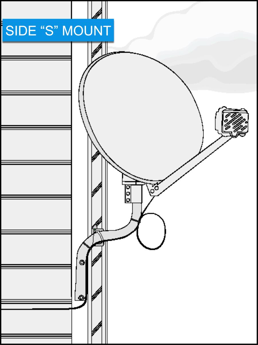
Take a picture showing a properly installed Side “S” Mount.
A correctly installed Side “S” Mount picture includes:
- The attachment to an approved, structurally sound surface
- Mount antenna to not impede any high-traffic areas
- Secured mast
- Zip-tie cable to the mast, including a service loop
- Connection the messenger/ground wire
Side “S” Mount specs:
- Attach to an approved, structurally sound surface (wood or composite only, southern facing corner, avoid touching the eave/roof with antenna)
- ODU is at least 3’ from the electrical panel and 20’ from the power lines
- Use only approved and matching ODU hardware
- Pre-drill holes required using a 1/4” wood bit
- Secure the mast to a corner stud with:
- Two 6” lags on S-tube
- Two 3” lags on L-bracket
- Seal all drilled holes with silicone
- Zip-tie cable to the mast, including a 6” diameter service loop
- Connect messenger/ground wire to a green ground screw on the “L” bracket
- Tighten all hardware completely
| Low Profile “STUB” Mount |
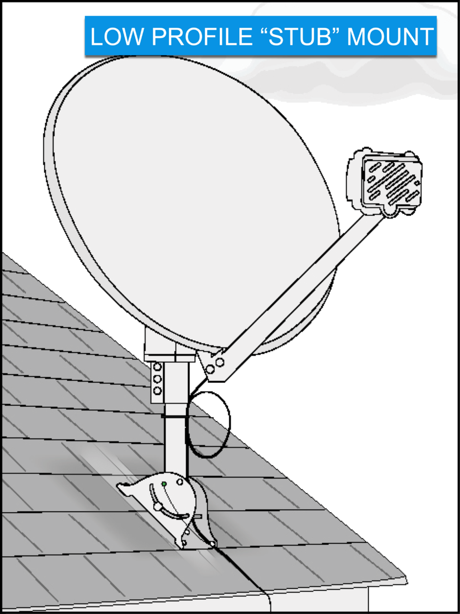
Take a picture showing a properly installed Low Profile “STUB” Mount.
A correctly installed Low Profile “STUB” Mount picture includes:
- The attachment to an approved, structurally sound surface
- Mount antenna to not impede any high-traffic areas
- Position of monopoles
- Secured footplate and monopoles
- Zip-tie cable to the mast, including a service loop
- Connection the messenger/ground wire
Low Profile “STUB” Mount specs:
- Attach to an approved, structurally sound surface: Sloped roofs only
- Asphalt shingles only
- Close to the roof’s edge
- Ideally not over living space
- The boom arm should be parallel with the rafter for best support
- ODU is at least 3’ from the electrical panel and 20’ from the power lines
- Use only approved and matching ODU hardware
- Pre-drill holes required using a 1/4” wood bit
- Secure the footplate to the roof with:
- Two 3” lags through center holes into the rafter
- Four 2” lags through corner holes
- Seal all drilled holes with tar-based sealant
- Zip-tie cable to the mast, including a 6” diameter service loop
- Connect the messenger/ground wire to a green ground screw on the footplate
- Tighten all hardware completely
| Brick Mount |
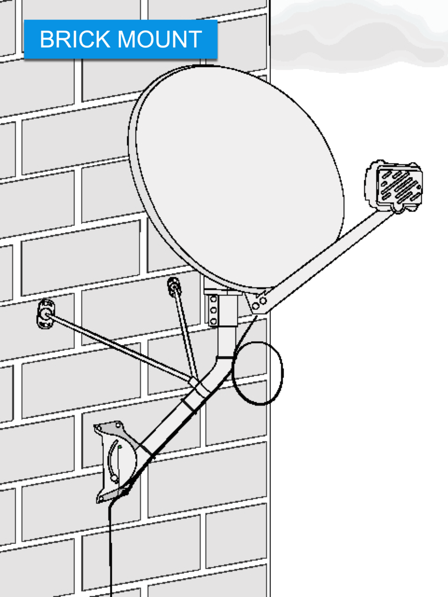
Take a picture showing a properly installed Brick Mount.
A correctly installed Brick Mount picture includes:
- The attachment to an approved, structurally sound surface
- Mount antenna to not impede any high-traffic areas
- Position of monopoles
- Secured footplate and monopoles
- Zip-tie cable to the mast, including a service loop
- Connection the messenger/ground wire
Brick Mount specs:
- Attach to an approved, structurally sound surface (load-bearing wall, away from corner/ door/window/top of wall, no chimneys)
- ODU is at least 3’ from the electrical panel and 20’ from the power lines
- Use only approved and matching ODU hardware
- Pre-drill holes are required using a 1/2-inch masonry bit
- Use a hammer to lightly tap a lag shield into the pre-drilled holes
- Seal all drilled holes with silicone
- Lags must not be drilled into mortar, or more than two lags in one brick
- Secure the footplate using four 2” lags in corner holes and proper anchors
- Position monopoles 2” below the bend, at an upward angle, forming a tripod
- Monopole plates secured by two 2” lags, using proper anchors
- Zip-tie cable to the mast, including a 6” diameter service loop
- Connect messenger/ground wire to a green ground screw on the footplate
- Tighten all hardware completely
| Under Eave Mount |
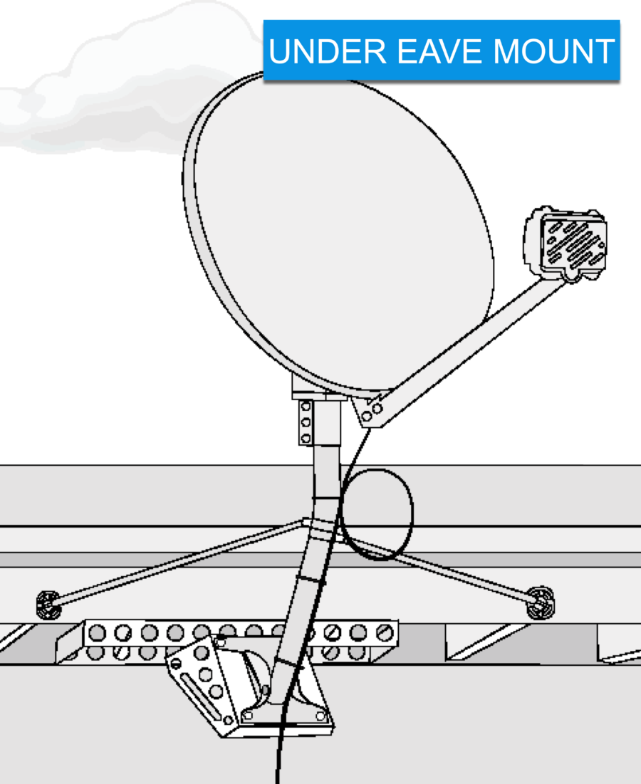
Take a picture showing a properly installed Under Eave Mount.
A correctly installed Under Eave Mount picture includes:
- The attachment to an approved, structurally sound surface
- Mount antenna to not impede any high-traffic areas
- Position of monopoles
- Secured footplate and monopoles
- Zip-tie cable to the mast, including a service loop
- Connection the messenger/ground wire
Under Eave Mount specs:
- Attach to an approved, structurally sound surface
- ODU is at least 20’ from power lines
- Use only approved and matching ODU hardware
- Pre-drill holes required using a 1/4” wood bit
- The following option is available:
- Slearo mount secured with four 3” lags
- Install the monopole per the manufacturer’s instructions
- Secure the monopole plates to adjacent rafters using two 2” lags
- Seal all drilled holes with silicone
- Zip-tie cable to the mast including a 6” diameter service loop
- Connect the messenger/ground wire to a green ground screw on the footplate
- Tighten all hardware completely
| Non-Pen Mount |
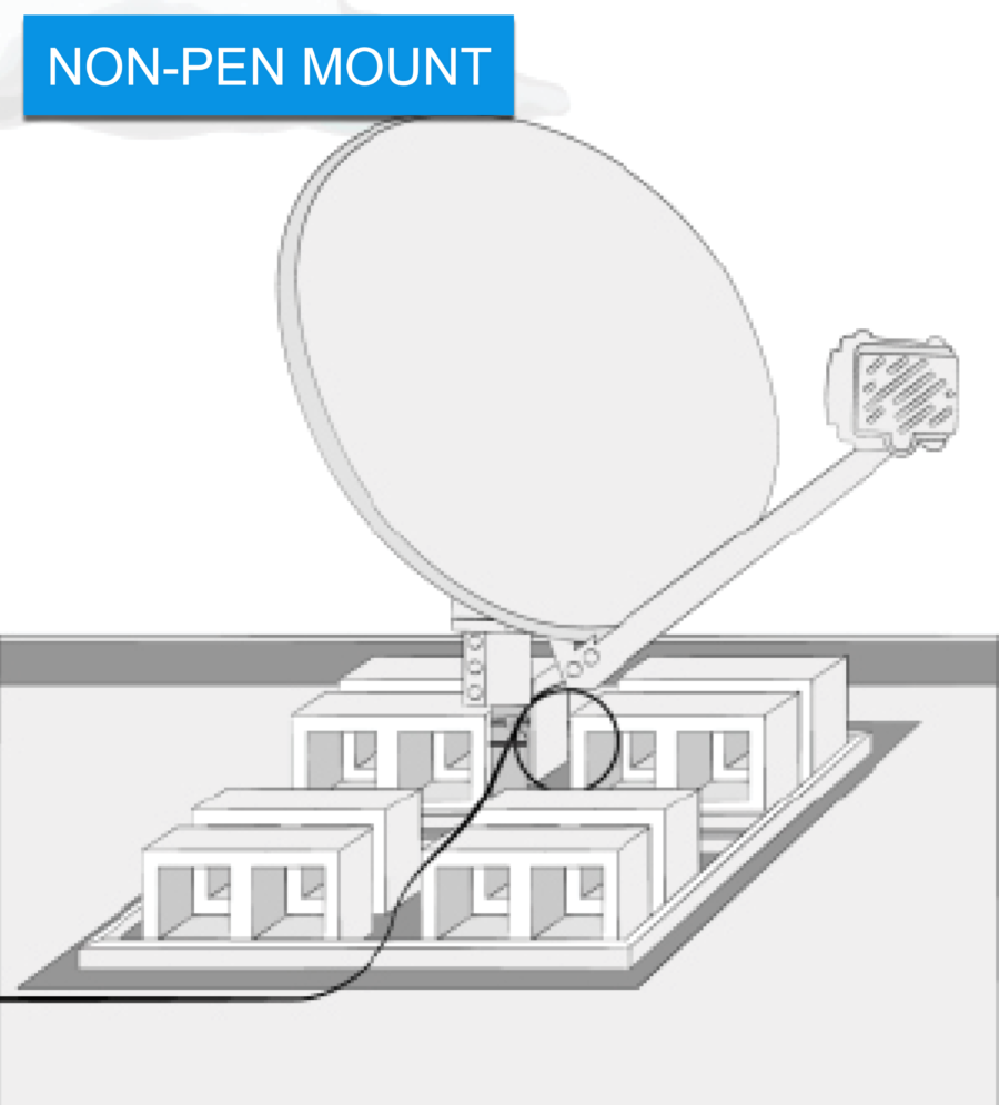
Take a picture showing a properly installed Non-Pen Mount.
A correctly installed Non-Pen Mount picture includes:
- The attachment to an approved, structurally sound surface
- Mount antenna to not impede any high-traffic areas
- Protective mat and cinder blocks
- Secured footplate and monopoles (if used)
- Zip-tie cable to the mast, including a service loop
- Connection the messenger/ground wire
Non-Pen Mount specs:
- Approved for flat roof, balcony, deck, patio, and ground use when a pole mount is not an option
- Use a protective mat on ALL locations
- If using monopoles, position the collars 2” below the bend, at a downward angle, forming a tripod
- Zip-tie cable to the mast, including a 6” diameter service loop
- Universal or stub mount based on location with snow as a consideration
- The surface must allow the mast to be leveled
- The location should not be prone to flooding
- ODU is at least 3’ from the electrical panel and 20’ from the power lines
- Cable must not pose a tripping hazard
- Requires eight 28-pound cinder blocks for ballast
- Connect the messenger/ground wire to a green ground screw on the footplate
- Tighten all hardware completely
| Rail Mount |
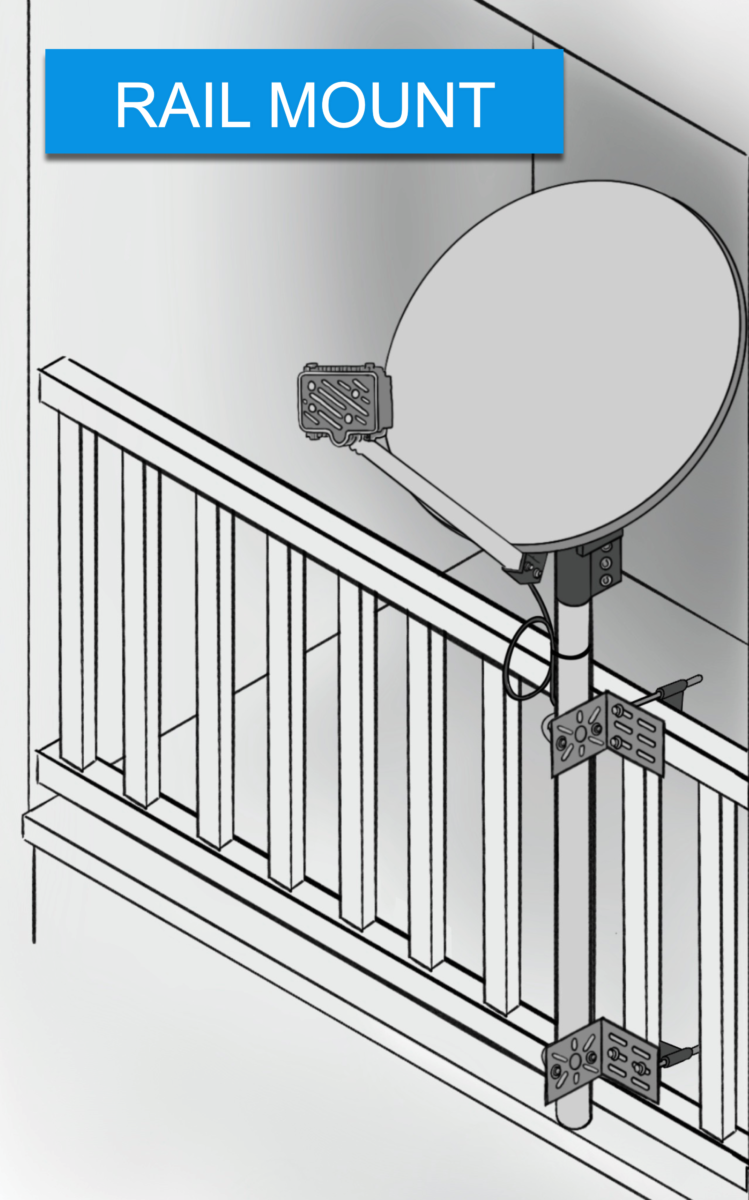
Take a picture showing a properly installed Rail Mount.
A correctly installed Rail Mount picture includes:
- The attachment to an approved, structurally sound surface
- Mount antenna to not impede any high-traffic areas
- Secured Position of the mast
- Zip-tie cable to the mast, including a service loop
- Connection the messenger/ground wire
Rail Mount specs:
- Attach to a structurally sound railing, preferably near a wall or post
- ODU is at least 3’ from the electrical panel and 20’ from the power lines
- Zip-tie cable to the mast, including a 6” diameter service loop
- Connect the messenger/ground wire to the L-bracket with a green ground screw
- Prevent hazards by properly routing and securing the coaxial cable
- Tighten all hardware completely
| Tile Roof Mount |
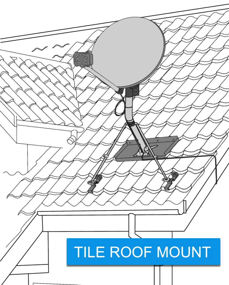
Take a picture showing a properly installed Tile Roof Mount.
A correctly installed Tile Roof Mount picture includes:
- The attachment to an approved, structurally sound surface
- Position of monopoles
- Secured footplate and monopoles
- Zip-tie cable to the mast, including a service loop
- Connection the messenger/ground wire
Tile Roof Mount specs:
- Attach to an approved, structurally sound surface on a sloped tile roof (clay or concrete tiles only)
- Avoid broken or cut tiles and use at least 3’ from any flashing
- ODU is at least 3’ from the electrical panel and 20’ from the power lines
- Requires use of tri-mast
- Place footplate 2 or more rows up from the eave
- Position monopoles 2” below the bend, at a downward angle, forming a tripod
- Zip-tie cable to the mast, including a 6” diameter service loop
- Connect the messenger/ground wire to a green ground screw on the footplate
- Tighten all hardware completely
| Pole Mount |
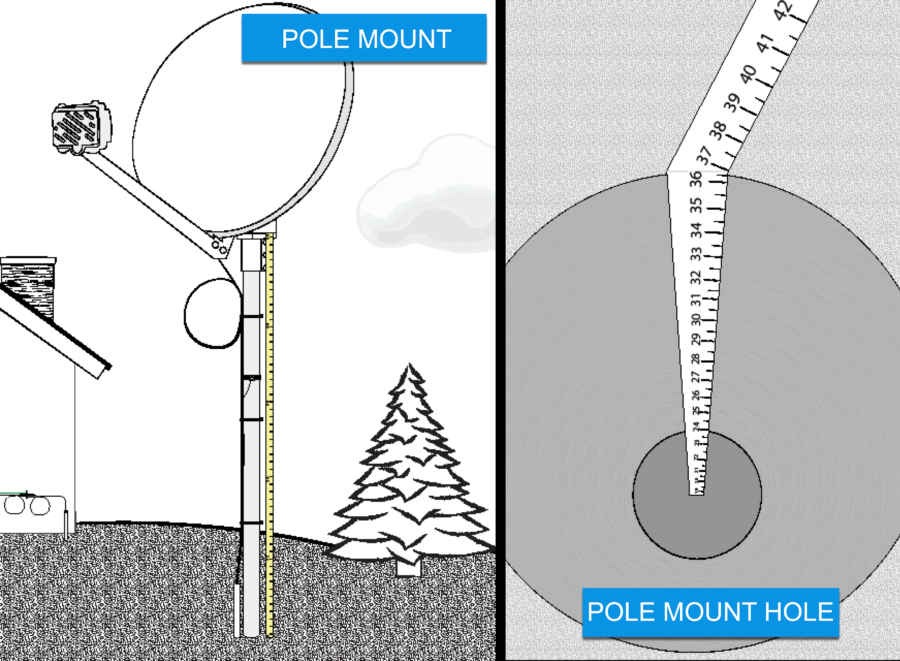
Pole Mount Photo Requirements
Take two (2) pictures showing a properly installed Pole Mount and hole.
A correctly installed Pole Mount picture includes:
- The Pole is installed in stable, solid ground
- Mount antenna to not impede any high-traffic areas
- Display of measuring tape for the entire pole
- Zip-tie cable to the mast, including a service loop
- Connection of the messenger or ground wire
Hole Photo Requirements
- The photo displays the hole measures 36” from the bottom to the top
- For concrete installation, the hole should appear 12” in diameter
- For foam installation, the hole should appear 3″- 4″ in diameter
Pole Mount specs:
- Install in stable, solid ground
- Use an approved pole
- Galvanized, with an anti-spin device
- A longer pole may be required to accommodate local frost levels greater than 36 inches.
- The portion of the pole above the surface level should never exceed 60″.
- The pole must be anchored with a non-rotating device installed at the base using at least 150 lbs. of quick-setting concrete OR 16 oz of approved expanding foam mix.
- Use 2 sweeps (1 at the pole, 1 at the house)
- If a non-flooded cable is used, it must be buried in conduit
- Zip-tie cable to the pole, including a 6” diameter service loop
- Connect the messenger or ground wire to a galvanized strap or a green ground screw on the flat side of the pole
- Tighten all hardware completely
Pole Mount Grounding
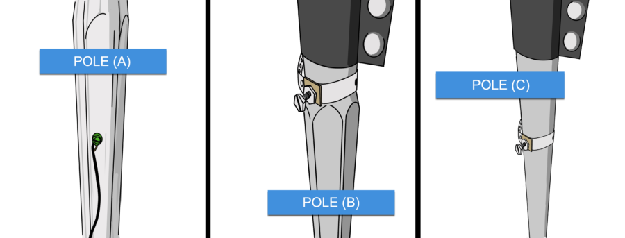
POLE (A)
The grounding to a pole (A), the green ground screw can be drilled directly into the flat side of a Hex pole. This grounding option is only available with a Hex pole.
POLE (B)
When grounding to a pole (B), a galvanized strap can be used at the top round part only of a Hex pole. This grounding option is available with both a Hex pole and a Round pole
POLE (C)
When grounding to a pole (C), a galvanized strap can be used in the middle area of a Round pole. This grounding option is only available with a Round pole.
02022024