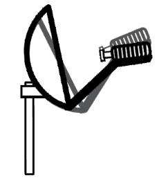
1.2M ODU/SurfBeam 2 Point and Peak Job Aid
Summary
This Job Aid covers:
Configure the SurfBeam 2 Modem and TRIA Point Elevation
Point Azimuth Peak Azimuth Peak Elevation Push/Pull Test
RX SNR in the Modem Browser Interface
This Job Aid supports all Installer audiences.
Videos
1.2 Meter ODU Assembly (English)
1.2 Meter ODU Point and Peak Demo (English)
Conjunto de ODU (unidad externa) de 1.2 metros (Español)
ODU de 1.2 Metros (unidad externa) Demostración de apuntar y ajustar elevación de Viasat (Español)
Conjunto do ODU de 1,2 metro (Portugués)
ODU 1,2 Metros (unidade externa) Demonstração de apontar e ajustar a elevação de Viasat (Portugués)
Required Tools
To point and peak a 1.2M ODU using the SurfBeam 2 (SB2) modem, an installer needs these tools:
- A computer with a Ethernet port and Ethernet cable
Note: This may be either the customer’s computer or the installer’s laptop.
- 17mm open wrench
- 17mm ratchet and socket
Configure the SurfBeam 2 Modem and TRIA
NOTE: To point and Peak with a Viasat WiFi Gateway or Modem see: https://eguide.field.viasat.com/viasat-2-viasat-wifi-gateway-point-and-peak-job-aid/
Recall that the TRIA receives its polarity setting from the SurfBeam 2 (SB2) modem, which in turn receives its satellite and beam assignments, and frequency set information from the Modem Key found on the work order.
These steps assume that the 1.2M ODU is sitting on its mount, and that cabling and grounding are complete.
Follow these steps to configure the SurfBeam 2 modem and TRIA prior to beginning the Point and Peak process.
Connect the computer to the SB2 modem using the Ethernet cable between the LAN ports on both devices
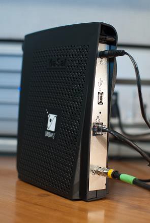
Connect the COAX cable between the Transmit (TX) port on the TRIA, and the TX port on the SB2 modem.
Note: If the SB2 modem has a single IFL port, use this port.
Plug the modem AC power cord into the power outlet. Wait approximately two minutes for the SB2 to power on.
Open the computer’s Internet Explorer browser and type this URL into the Address bar:
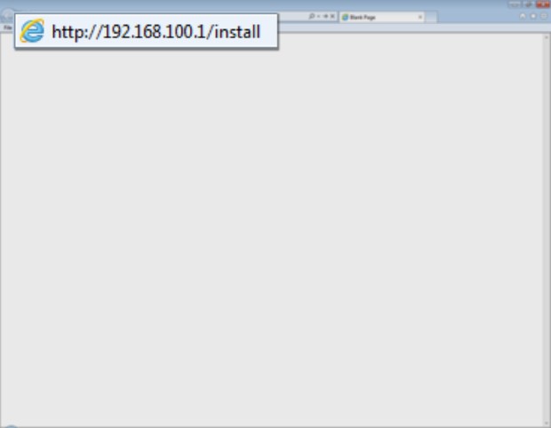
Click the forward arrow in the Address bar. The modem enters the Installation Mode.
Note 1: Internet Explorer or Mozilla Firefox are the preferred browsers for this step. Other browsers may have different results.
Note 2: If a ‘website not found’ error appears, click the browser’s refresh button until the page appears
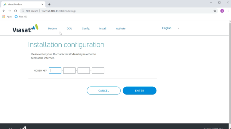
Find the 16-digit Modem Key on the work order, and type it into the fields and click Enter.
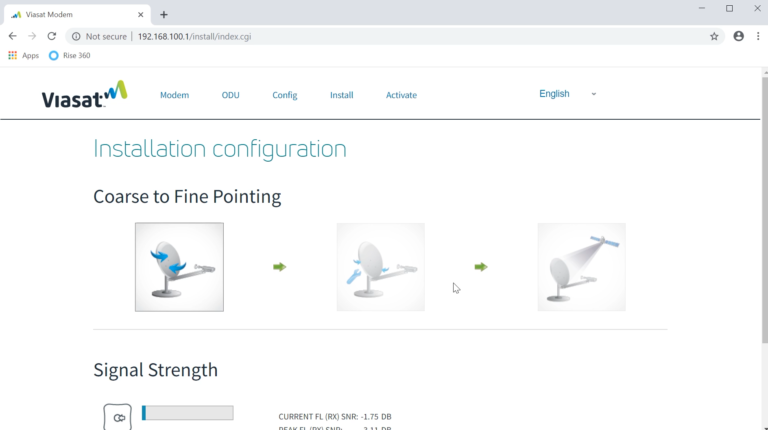
The Installation Configuration page changes.
Confirm that these two events are happening:
- The SB2 modem’s RX and LAN lights are flashing.
- The TRIA is emitting the ‘heartbeat’ tone
The SB2 and TRIA are ready for the Point and Peak process.
Point Elevation
The following information reviews the steps to complete the point (coarse) antenna Elevation adjustment.
Setting the Elevation can be done during assembly or after the ODU is completely assembled.
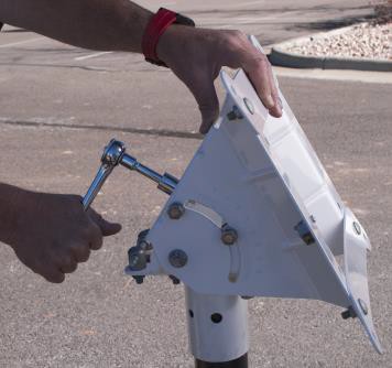
All four elevation lock down bolts need to be loosened and their four associated lock washers disengaged prior to beginning the adjustment of the elevation process.
Do not lockdown the elevation bolts until finished with adjusting the elevation.
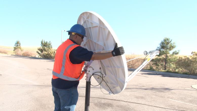
Point Azimuth
Point the antenna to the course azimuth.
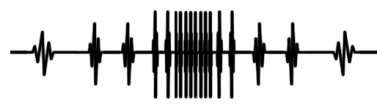
SB2 TRIA tone sequence
Recall that the SB2 modem must learn about its frequency set. This happens when the installer sweeps the antenna from each side of the azimuth or the elevation.
| Inside the Frequency Set the TRIA emits | Outside the Frequency Set the TRIA emits | |
| During Point azimuth | Ring Ring, low/slow, high/fast, high/steady | Heartbeat |
| During Peak azimuth | Low/slow, high/fast, high/steady | None – always inside the frequency set |
Follow these steps to point the Azimuth of the 1.2M ODU.
Sweep the antenna from side to side, checking the tightness of the three flange nuts on the mount canister. The antenna should move, but not too easily. Tighten or loosen the flange nuts as needed.
Note: After placing the antenna on the mount tube, the Installer aligned it to the desired compass setting.
Sweep the antenna to the right, about 10 degrees away from the line-of-sight selected during the Site Survey.

Sweep the antenna toward the left, listening for the TRIA to emit the ‘ring ring’ tone. Continue sweeping the antenna toward the left until the TRIA emits the ‘heartbeat’ tone. Stop, as this is the end of the first learning pass.

Note: Disregard any ‘beep bop’ tones. The TRIA does not recognize these satellites.

Reverse the direction of the sweep, and listen for the TRIA to progress through the tone sequence. Stop the sweep when the TRIA emits the heartbeat tone. This is the end of the second learning pass.

Note: Use a slow, consistent tension on the antenna during this sweep. Not all of the tones may be heard.

Reverse the direction of the sweep again, now sweeping to the center, and listen for the TRIA to emit the high/steady tone. The antenna is now in the center of the beam.

Finish this step by tightening the Flange bolts, starting with the top to maintain an even pressure on the Tube canister.
Note: The high/steady tone may dip while tightening the Flange bolts. If the tone does not return to the high/steady, then repeat the step. Remember to reset the modem’s learning by sweeping the antenna away from the satellite, and holding the Inclinometer bracket over the feed horn.
Peak Azimuth
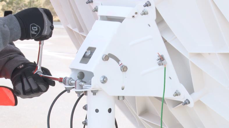
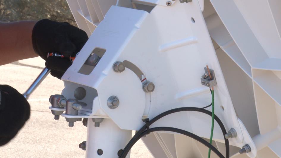
Loosen the Azimuth base plate bolts using a 17mm ratchet.

Using a wrench, rotate the hex head of the Azimuth fine- adjust bolt.
Important: Do not pass the low/slow tone when peaking the ODU.

Sweep the antenna toward the left, listening for the TRIA to emit the low/slow tone, which means that the antenna has found the far edge of its frequency set.

Stop, as this is the end of the first fine-tune learning pass.

Reverse the direction of the sweep, now sweeping to the right, and listen for the TRIA to progress through the tone sequence. Stop the sweep when the TRIA emits the low/slow tone. This is the end of the second fine-tune learning pass.
Note: Because this is a fine- tune pass, all tones should be present. Periodically pause and wait for the modem to evaluate the information coming from the antenna.

Reverse the direction of the sweep again, now sweeping to the center, and listen for the TRIA to emit the high/steady tone. The antenna is now in the center of the beam.

Finish this step by tightening the Azimuth base plate bolts.
Note: The high/steady tone may dip while tightening the base plate bolts. If the tone does not return to the high/steady, then restart the Point and Peak process.
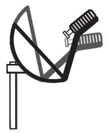
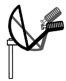
Remember to reset the modem’s learning by sweeping the antenna away from the satellite, holding the Inclinometer bracket over the feed horn, and then re-centering the Azimuth fine-adjust bolt.
The following information reviews the steps to complete the peak (fine) antenna Azimuth adjustment.
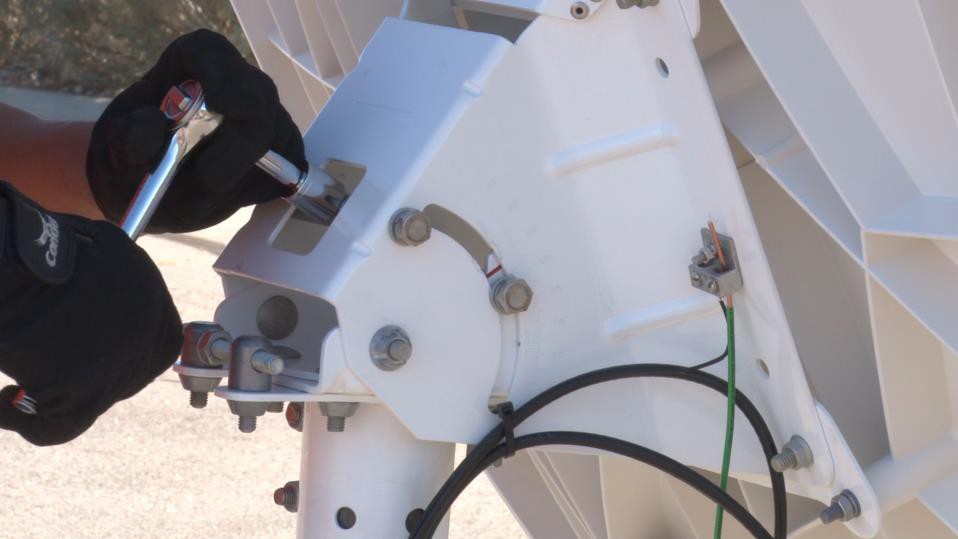
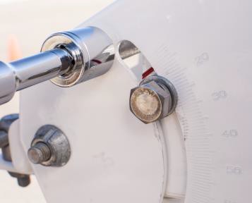
Slightly loosen the 4 Lockdown Nuts in the Arched Slots on sides of the Elevation Bracket
Use the wrench on the Elevation rod nut to adjust the elevation up or down.
Caution: Do not pass the low/slow tone when peaking the ODU.
Sweep the nut on the Elevation rod such that the TRIA drops ,and listen for the TRIA to emit the low/slow tone, which means that the antenna has found the far edge of its frequency set.

Stop, as this is the end of the first fine-tune learning pass.
Reverse the direction of the sweep, now sweeping to raise the TRIA, and listen for the TRIA to progress through the tone sequence. Stop the sweep when the TRIA emits the low/slow tone. This is the end of the second fine-tune learning pass.

Note: Because this is a fine-tune pass, all tones should be present.
Periodically pause and wait for the modem to evaluate the information coming from the antenna.
Reverse the direction of the sweep again, now sweeping to the center, and listen for the TRIA to emit the high/steady tone. The antenna is now in the center of the beam.
Finish this step by tightening the same bolts and nuts. Start with the top nut on the Elevation rod, and then the Elevation Lock Down bolts.

Note: The high/steady tone may dip while tightening the base plate bolts. If the tone does not return to the high/steady, then restart the Point and Peak process.
Push/Pull Test
Important: An installer always completes two tests before obtaining Modem Lock: a Push/Pull test and a review of the RX SNR in the Signal Strength section of the Modem Browser Interface. Passing these tests prevents delays in Modem Lock and Provisioning because they confirm that the antenna has aligned correctly during Point and Peak.
From behind the antenna, gently push and pull each side of the antenna.
Gently push and pull the top and the bottom of the antenna
The test passes when the TRIA’s high/steady tone drips every time pressure is added to the antenna. The tone returns to its high/steady state when the pressure is removed.
If the tone rises, the alignment is not correct the installer must repeat the Point and Peak process. Remember to reset the modem’s learning by sweeping the antenna away from the satellite, holding the Inclinometer bracket over the feed horn, and then re-centering the Azimuth fine-adjust bolt.
RX SNR in the Modem Browser Interface
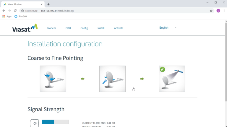
During the Point and Peak process, the Modem Browser Interface records the current and the peak RX SNR levels in the Signal Strength section. These two levels will match when an antenna is aligned correctly.
If these two levels do not match, repeat the Point and Peak process. Remember to reset the modem’s learning by sweeping the antenna away from the satellite, holding the Inclinometer bracket over the feed horn, and then re-centering the Azimuth fine-adjust bolt.
Note: These levels rise and fall in real time, so differences +/- 0.5dB are acceptable. Differences greater than 0.5dB should be seen as a failed Point and Peak.