Antenna Cabling Job Aid
Go to: Cabling videos
Summary
This Job Aid covers:
Viasat Coaxial Cable and Connector Requirements
Attaching Compression Connectors
Attaching the Cable to Outside Walls
This Job Aid supports all Technician audiences.
Viasat Coaxial Cable and Connector Requirements
Cable Type and Quantity
The following information highlights the Viasat cable and connector model requirements. For a complete list of all requirements, refer to the
Viasat Coax Cable Specification, available in the eGuide.
Important! Copper Clad Steel (CCS) Coax is not acceptable. Installations using CCS fail within the warranty period so technicians will be required to return and make a warranty repair.
SB2, SB2+, and VWG: One cable length acts as both the Transmit (TX) link and the Receive (RX) link.
WildBlue and SB Modems: One cable length is for the TX link and one is for the RX link.
Other Important Cable Requirements
- This cable type has a maximum bend radius of 3 inches, which is the same as a 6-inch diameter.
- Never put a 90-degree bend in any cable run.
- The cable(s) must not exceed the maximum length of 150 feet (45.72 meters) from the TRIA to the modem.
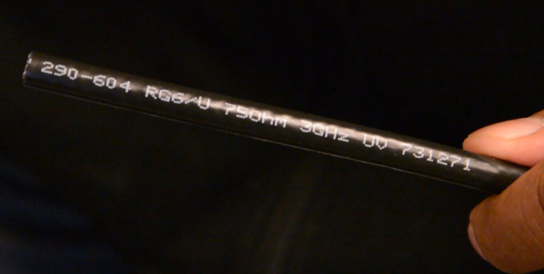
- The cable(s) must have the following printed on the cable:
- Frequency
- RG number
- Copper type
- Impedance
Connector Requirements
- The cable(s) must be terminated with RG-6 inline, 3.0 GHz or higher, F-type linear compression connectors that are fully weather-sealed. See Viasat Connector Specifications, for additional information.
| Component | Component Supports | Example |
|---|---|---|
| Center Core (conductor): • Support voltage drops less than 6.7 volts • 75 Ohm impedance • Solid copper | Voltage between the Satellite Modem and the TRIA Note: Copper-clad steel center conductors drop excessive voltage and cannot provide the correct voltage to the TRIA | 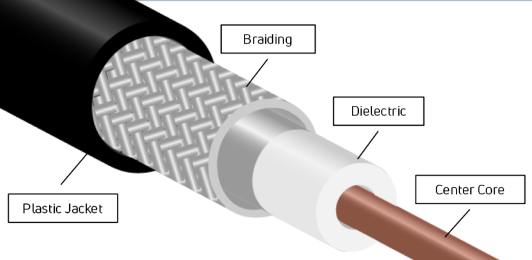 |
| Dielectric insulator: • Must support 3.0 GHz (or higher) IF frequency | Intermediate Frequency (IF) frequency between the satellite modem and the TRIA |
|
| Metallic Shield (outer shield): • Minimum of 60% braid | Grounding between the antenna and the dual ground block |
|
| Compression Connectors • RG6 linear compression connector type • Fully weather sealed • Meets COAX Connector Specifications Note: Crimp connections are not acceptable. | Connectivity between hardware and cable runs | 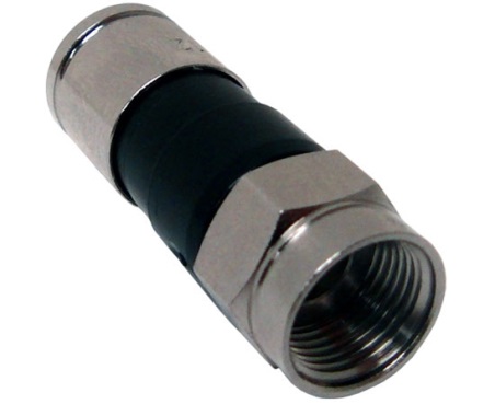 |
Attaching Compression Connectors
While Coax compression connectors vary slightly from manufacturer to manufacturer, the process for attaching the connectors is similar.
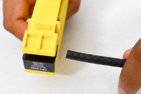
Cut the end of the cable off squarely with cable cutters. Then, remold the mashed cable so that it is round again.
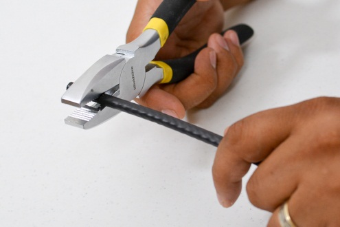
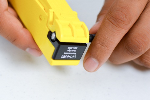
Place the cable in a 2-blade strip tool, with the end flush against the side of the tool. Notice in the image below that the cable prep tool shows the direction for loading the cable. Squeeze the tool, so that the blades pierce the outer jacket. Twirl the cable prep tool in a forward motion around the cable 3 to 5 times. Do not turn the tool backwards (counter clockwise). Carefully, remove the prep tool.
Important! Do not pull cable out of prep tool as this could cause damage to cable and tool.
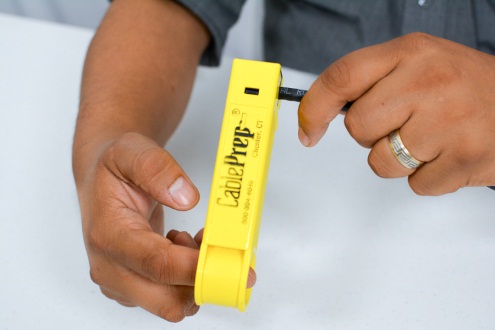
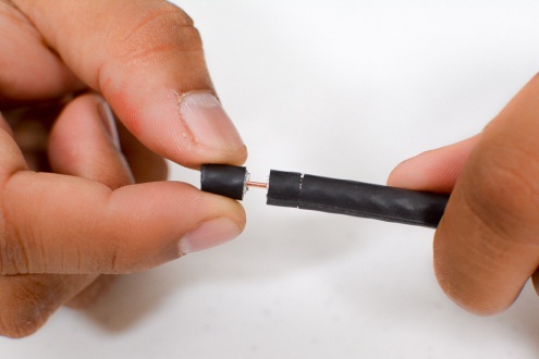
If you have used the prep tool correctly, the cable now has two cuts. The cut closest to the end of the cable has cut completely to the center core. The second cut has cut only the outside plastic jacket, leaving the braid intact.
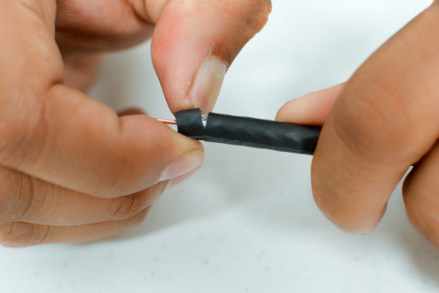
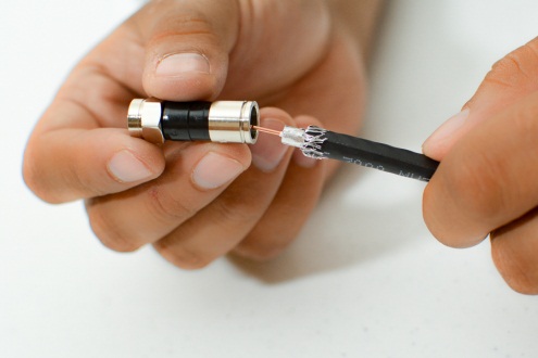
Expose the center core from the first cut, and then carefully remove the outer plastic from the second cut. Leave the braid and layer of foil surrounding the dielectric.
When you have completed this step, the cable will have ¼ inch of stripped center conductor, and ¼ inch braid covering ¼ inch of dielectric.
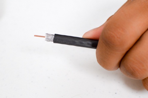
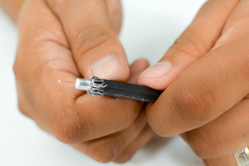
Carefully spread the braid away from the foil, and lay the braid evenly back onto the jacket. Do not remove the braid, or allow the braid to bunch up on one side of the cable.
Slide the cable into a connector (3.0 MHz or higher), easily, without adding excessive pressure, until the dielectric is flush with the floor of a connector. The center conductor should extend a little beyond the edge of the connector.
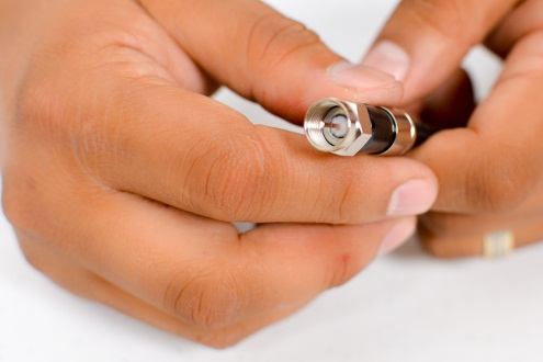
Important: Common connector failures are:
- Removing the foil
- Braid wire touching or wrapped around the center conductor
- Braid wire extending beyond the connector casing
- Center conductor too short
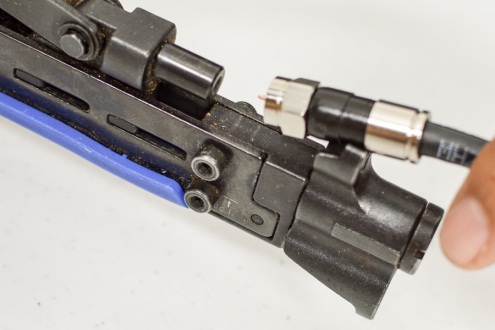
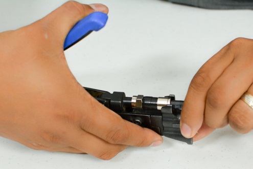
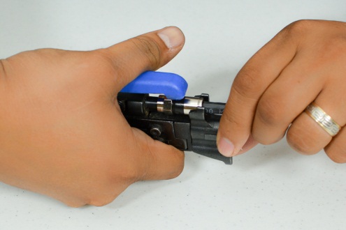
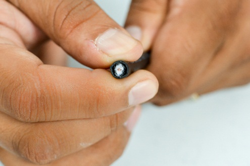
Slide the assembled connector into the compression tool. Squeeze the handle until the ring seats all the way into the connector. You should hear or feel a “click” as it pops into position.
Remove the completed cable from the compression tool.
If the cable prep tool was used correctly at the beginning, then the center conductor is the proper length and no trimming is required.
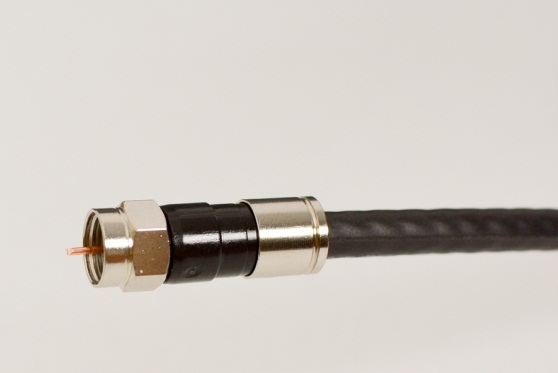
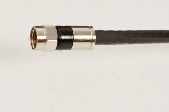
Before Compressing After Compressing
Applying Torque
Torque is the turning or twisting force applied to a fitting. As torque is applied, it creates a tension between the two objects that are being clamped together, such as nut and screw threads. The goal of torque is to provide the proper clamping force to prevent slippage, water seepage, etc.
Follow these steps to apply torque correctly.
Use a 30 in/lb. 7/16 single-setting, click-type open torque wrench.
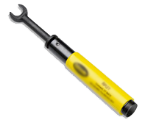
Place the open wrench on the connector, and rotate the wrench until you feel and hear the ‘click’. This indicates that the correct amount of tension has been achieved.
Use the torque wrench to tighten the following connections:
- Attaching coax to TRIA,
- Attaching coax to ground block
- Attaching coax to wall plate
NEVER torque the modem coax connections – hand-tighten these connections
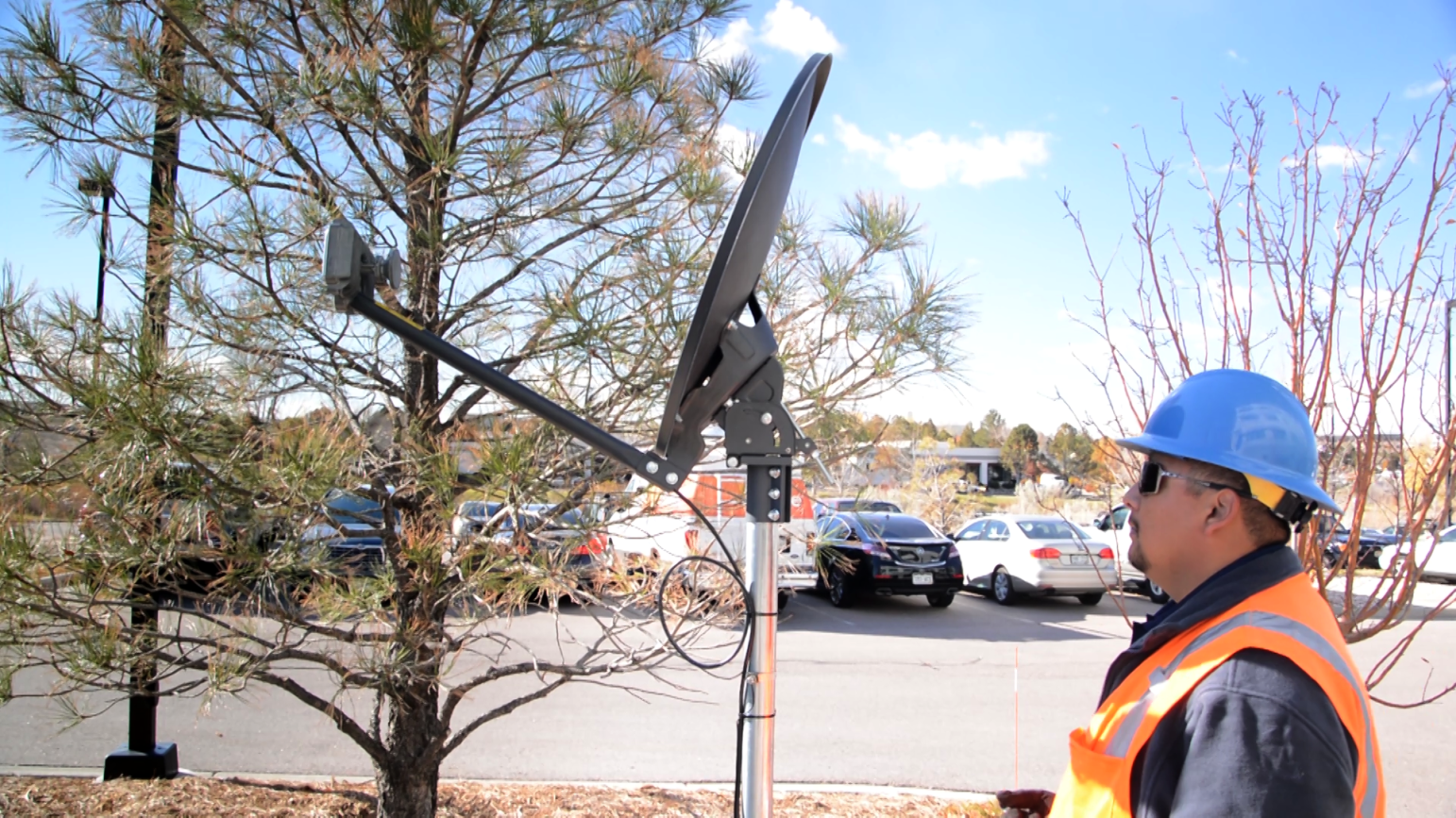
Exterior Cable Run
The following information outlines the steps used to install the cable run by attaching coax cable between several points. The cable run begins at the IFL port(s) (Intermediate Frequency Link) on the TRIA and ends at the IFL port(s) on the modem. The number of IFL ports depends on the TRIA and modem.
- Tighten all critical connections with a 30 inch/pound (in/lb) open torque wrench (as described above)
- This decreases the possibility of moisture entering through the connections
- This prevents over tightening, which damages the IFL port
- Hand-tighten the connection(s) at the modem
Beginning at a Single IFL TRIA
Add a connector to one end of the coax, and thread it through the boom arm.
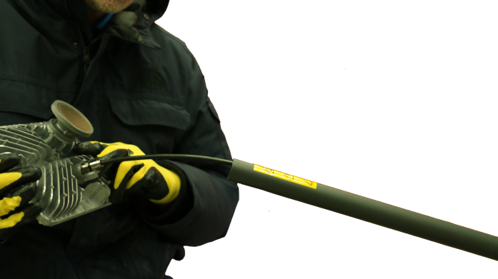
Connect the coax to the IFL port inside the TRIA’s collar.
Remember! Tighten the connection with 30 in/lb torque after connecting the coax cable.
Slide the Boom Arm over the coax cable and onto the TRIA collar. Add the two hex screws (found in the box) to attach the Boom Arm to the collar.
Important! The screws included in the box must be used.

Create Service Loop at the Antenna Mast Tube
After connecting the coax to the TRIA, create a service loop at the back of the Boom arm. Recall that the bend radius is 3 inches, so the service loop cannot be smaller than 6 inches.
Secure the cables to the Mast Tube using outdoor-rated zip-ties.
Attaching the Cable to Outside Walls
For a wall/roof mount, start at the Mount Bracket.
For a pole mount, use the correct procedure for burying the cable, adding sweeps and conduit to the cable trench, as described in the Pole Mount Job Aid.
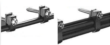
For horizontal cable runs, attach the cables to the wall surface using screw clips every 18 to 24 inches.
For vertical cable runs, attach cables to the all surface with screw clips every 30 to 36 inches.
Note: Nail cable clips are also acceptable.
Keep the cable run as straight as possible, but remember to use the correct bend radii. Follow horizontal and vertical elements (such as the siding) at every opportunity. Diagonal or aerial cable runs are not allowed.

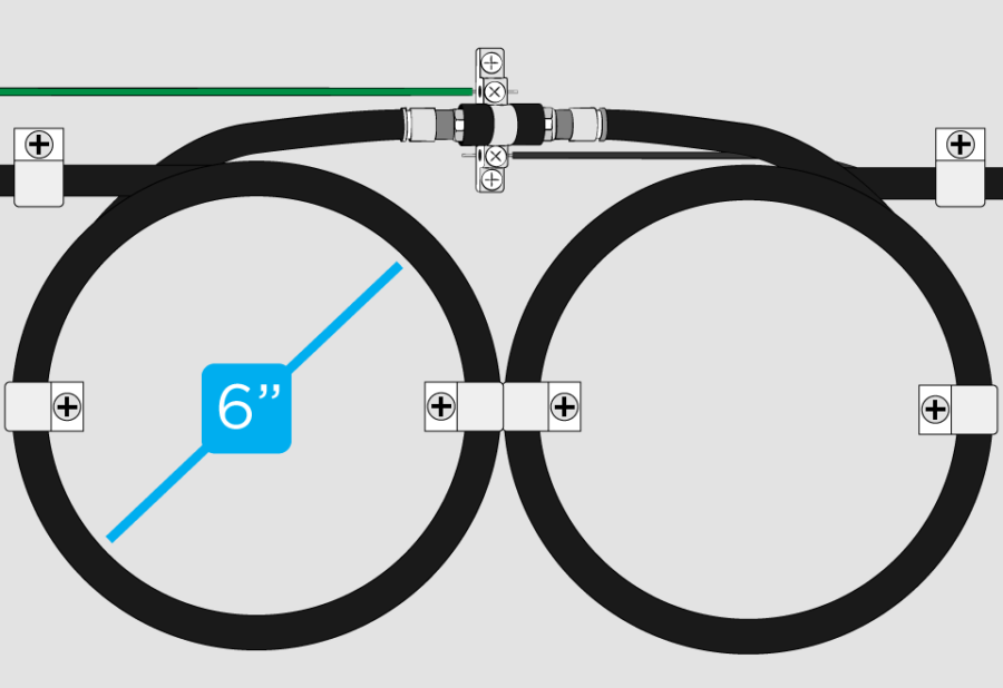
Attach the ground block (dual or single, 3.0MHz or higher) to the building, within 20 feet of the building ground.
Within 8-10 inches of the ground block, create a 6-inch service loop.
Wrap the leading edge of the coax over the service loop such that it lies neatly when connected to the ground block.
Slope the service loop in such a way that the water drains away from the ground block.
Use cable screw clips to attach the service loop to the wall.
Cut the cable at the point where the cable will connect with the ground block.
Attach a linear compression connector on each cable end.
Add weather boots (seals) to all IFL ports on the ground block, and then connect the cables to the ground block.
Remember! Tighten the connection(s) with 30 in/lb torque after connecting the coax cable.
Important! If you are using a dual ground block, but only have one cable run, the unused IFL ports on the ground block must have weather boots AND terminators, which protect the unused ports from weather.
About a foot below the point of entry to the building, stop attaching the cable to the wall to allow the cable to curve gently into the pass-through bushing, avoiding a 90-degree bend.
Remember! Never put a 90-degree bend in any cable run.
Finishing the Cable Run
Important: A standard installation supports one exterior wall and one interior wall/floor penetration.
Exterior Penetration
Drill from inside the building to create the wall penetration. After returning outdoors, thread a feed-through bushing onto the leading edge of the coax, and push it into the exterior wall. Add an exterior silicone sealant to the bushing before pushing it into the wall penetration.
Interior Single Wall Plate
Make sure the cable run through the wall does not cause a bend or crimp in the cable.
At the inside wall plate location, pull the cable through the hole in the sheet rock and push the cable through a hole in the single wall plate, allowing enough cable length to reach the modem installation location.
Secure the single wall plate per manufacturer instructions.
At the modem installation location, cut the coax cable to length.
Add a compression connector to the end of the coax and hand-tighten the coax to the modem’s IFL port(s). Torque is not used on this connection.
Interior Single Connector Wall Plate
Cut the coax cable so that no more than three inches of cable protrude from the wall.
Secure the cable to the connector on the back of the wall plate.
Carefully push the cable into the wall and secure the wall plate per manufacturer instructions. If the cable is the correct length, it forms an arc inside the wall. If the cable is too long, there will be cable bends over the maximum bend radius.
Measure the distance between the wall plate and the modem location.
Cut an appropriate length of coax cable to create an extension cable, and attach a compression connector on all cable ends. Attach one end of the coax cable to the wall plate using the 30 in/lbs. torch wrench.
Hand-tighten the coax cable to the modem’s IFL port.