Installation Grounding Job Aid
Go to: Grounding video
Minimum Grounding Requirements
The National Electric Code (NEC) requires bonding for all satellite antenna systems. Both the antenna and the COAX cables require a ground.
Important: The following represents Viasat’s minimum grounding requirements. All grounding must meet these requirements, along with all NEC, State, and Local specifications. Where there is a discrepancy between these authorities, the most stringent requirements must be followed.
Important: The total length of the ground run from the ground block to the building ground must not exceed 20 feet.
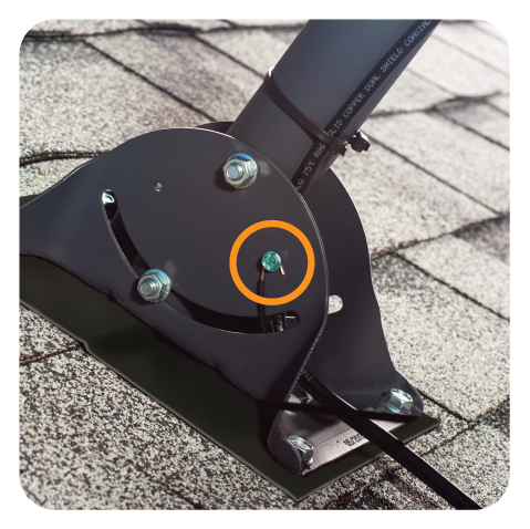
Antenna Grounding Requirements when using the Footplate
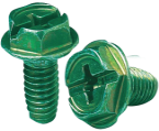
Attach a fine-thread green ground screw to the designated hole in the footplate.
Scrape paint if necessary, so that metal touches metal. The ground run begins at the ground screw.
Important! Per NEC code, do not use a self-tapping screw for grounding. A self-tapping screw does not provide enough contact with the foot plate.
NEC Code section: 250.8(5), 250.8 (6)
Attach the #17 messenger wire to the green ground screw. This wire becomes the ground for the antenna.
If desired, a #10 solid copper wire may be used instead of the #17 messenger.
Important! Do not coil the ground/messenger wire.
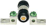
Using two screws, attach a ground block (3.0 GHz or higher) with the screw holes vertical, to an appropriate location on the building. Leaving the ground block unattached is not to NEC code.
The ground block must have two ground wire terminating ports
- 1 for the #17 Messenger, and
- 1 for the #10 Green ground wire
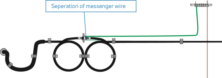
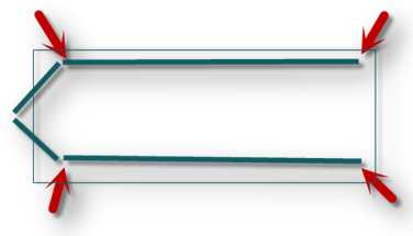
Separate enough #17 messenger wire from the COAX so that the COAX can neatly create the required 6” service loop.
Create the service/drip loop with the COAX; however, do not include the messenger wire in the service loop. The #17 messenger wire can never follow the service loop as this can create a ground imbalance.
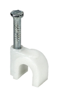
To support the COAX run, use screw cable clips:
- Horizontal: Every 18-24 inches
- Vertical: Every 36 inches
Note: Nail cable clips are also acceptable.
Terminate the #17 messenger wire in one of the ground wire ports using the screws on the ground block.
Do not share ground ports; only one wire per port.
Note: The #17 messenger wire now runs from the ground screw on the footplate to the ground block on the wall.
Connect a separate piece of #10 solid copper wire to the second ground wire port using the screw on the ground block.
Terminate the #10 solid copper wire to the building ground, according to the Building Ground Requirements described below.
Run the #10 ground wire for the shortest distance possible, as straight as possible, with no 90 degree bends. To secure this ground wire to the building, use a ground screw cable clip:
- Horizontal: Every 18-24 inches
- Vertical: Every 36 inches
Note: The distance between the ground block and the building ground must be less than 20 feet.
NEC Code sections: 810.21(C), 810.21(D); 820.100(A)(4), 820.100(A)(5)
Antenna Grounding Requirements when using a Pole Mount
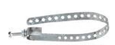
Attach a galvanized ground strap around the pole approximately 3 inches below the base of the AZ/EL canister.
Code requires the straps be the same metal type as the pole. Scrape away all paint so that metal contacts metal all the way around the pole.
The ground run begins at the ground strap.
Note: When two different metals are in contact in a corrosive environment, one of the metals experiences accelerated galvanic corrosion while the other metal remains galvanically protected. Eventually this breaks the bond removing all grounding potential.
NEC Code sections: 250.12
Separate enough messenger wire from the COAX so that the COAX can neatly create the required 6” service loop.
Create the service/drip loop with the COAX; however, do not include the messenger wire in the service loop. The messenger wire can never follow the service loop as this can create a ground imbalance.
Insert the #17 messenger wire in the ground screw on the ground strap. This wire bonds the COAX.
If desired, a #10 solid copper wire may be used instead of the #17 messenger.
Note: If this option is used, the ground wire must be carried in conduit from the pole to the ground block. It may not be left exposed.
Use weather-resistant ties to secure the COAX and messenger to the pole. Make sure that there are only soft curves and no 90-degree bends.
Important! Do not use a self-tapping screw to bond the #17 ground wire, as this does not follow NEC code.
Run the COAX and the messenger (or copper wire) through the sweeps, and place in the trench as required in the Pole Mount Job Aid.
Important! #10 ground wire, as well as non-flooded cable, must be carried in PVC conduit.
Using two screws, attach a ground block (3.0 GHz or higher) to an appropriate location on the building. Leaving the ground block unattached is not to NEC code.
The ground block must have two grounding ports.
Terminate the #17 messenger wire in one of the ground wire ports using the screws on the ground block.
Do not share ground ports; only one wire per port.
Note: The #17 messenger wire now runs from the ground strap on the pole to the ground block on the wall.
Connect a separate piece of #10 solid copper wire to the second ground wire port using the screw on the ground block.
Terminate the #10 solid copper wire to the building ground, according to the Building Ground Requirements described below.
Terminate the #10 solid copper wire to the building ground, according to the Building Ground Location Requirements described below. To secure this ground wire to the building, use a ground screw cable clip:
- Horizontal: Every 18-24 inches
- Vertical: Every 36 inches
Note: The distance between the ground block and the building ground must be less than 20 feet.
NEC Code sections: 810.21(C), 810.21(D); 820.100(A)(4), 820.100(A)(5)
Building Ground Location Requirements
These types of building grounds are acceptable for grounding a Viasat system.
An Intersystem Bonding Termination (IBT) installed by a licensed electrician available to terminate the #10 solid copper wire.
Important: If the IBT is available, it is the only option for grounding. All other ground sources would not be to NEC code.
Important: A technician may not install an IBT.
NEC Code sections: 250.94, 810.21(F)(1), 820.100(B)(1)
An Electrical Service electrode (building ground) rod must be back-bounded to the building’s electrical panel.
Install a Ground Lug on the #6 bare copper wire previously installed between the ground rod and electrical panel.
Important! A technician may not install an electrode; the electrode must be pre-existing and back bonded to the main electrical panel feeding the building.
NEC Code sections: 820.100(B)(6), 810.21(F)(2)(6)
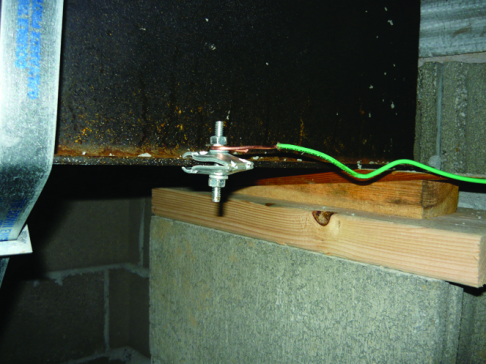
A non-flexible metallic power service raceway. The conduit must be solid. Flexible conduit cannot be used as a grounding point. The ground strap must be of the same metal. Scrape away all paint so that metal contacts metal all the way around the raceway.
NEC Code sections: 810.21(F)(2)(4), 820.100, 250.50
An Electrical Panel Clamp attached to the side or top of the metal electrical service panel, as long as the clamp does not impede opening the service panel door, or risk the ground wire being cut when an electrician attempts to open the panel.
Caution: Never drill into an electrical service panel.
NEC Code section: 820.21 or 820.100
Important! Exhaust all other possible ground options before choosing this. If any other options are available, using an I-beam Clamp will fail an audit.
An I-beam Clamp on a structure’s main metal frame can provide ground on mobile homes only. When grounding to a mobile home, install the clamp at the end of the I-beam. Never install the clamp in the middle or the front angled part of the frame, or on the straps that surround the beams.
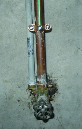
A building water main source that is within five feet of the entry to the structure, and only if the water pipe is metal and in direct earth contact for at least 10 feet before entering the building. Using the water main beyond five feet renders the ground useless and does not protect the customer and the system.
Important!
- The water pipe clamp and water pipe must be made of the same metal.
- Attaching a ground wire to a water valve/spigot is not acceptable.
NEC Code sections: 250.2, 810.21(F)(2)(2), 820.100(B)(2), 250.52(A)(1)
Zone of Protection (ZOP)
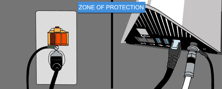
If using the Zone of Protection (ZOP), the antenna location must meet NEC ZOP requirements.
- A properly secured bond to the electrical outlet wall plate.
- Use an adapter to convert the 3-prong grounded cord to a 2-prong cord.
- Outlet tester indicating properly wired circuit.
References
National Electrical Code, Nfpa 70 (2014 ed.). (2015). Quincy, MA: National Fire Protection Association (NFPA).