Brick, Block, or Poured Concrete Wall Mount Job Aid
Approved surfaces for a wall mount are walls made of brick, cinder block, hollow block, or poured concrete.*
*Other approved surfaces covered in separate job aids.
Structural Elements
The approved structural elements for a wall mount are brick or poured concrete.
Important considerations
DANGER! Locate power lines before you start the installation. These include overhead and underground power lines, electric lights, and power circuits.
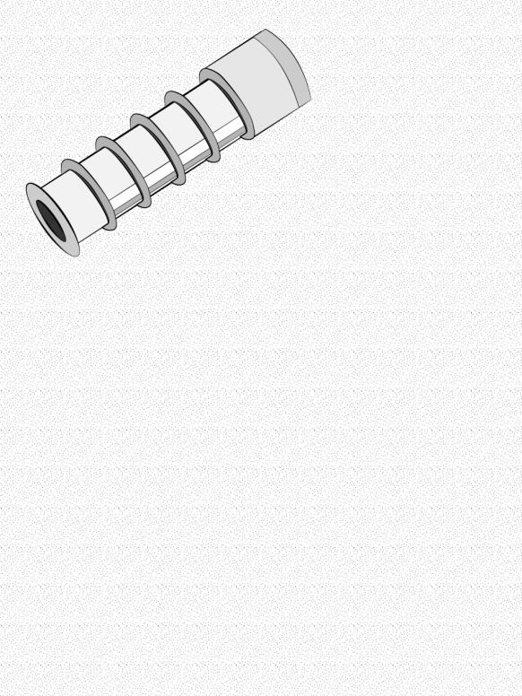
- Use double expansion wall anchors (lag shields)
- Never place anchors:
- In the mortar between blocks/bricks
- In poured concrete seams
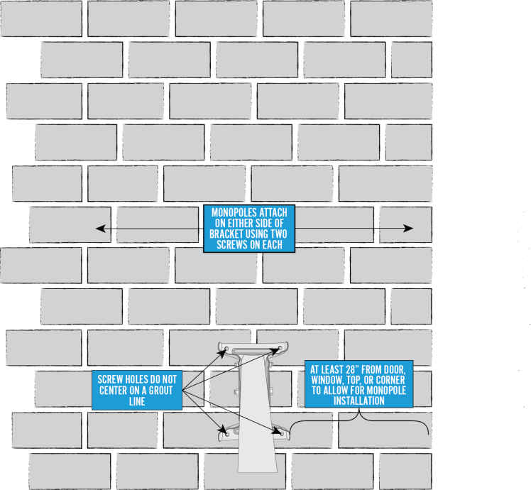
- To allow for mounting the monopoles, the center footplate mount anchors must be installed at least 30 inches from the edge of a:
- Door
- Window
- Building corner
- Wall
- Position the mount so that:
- The building eave or overhang will not block or partially shadow the line of site
- The bottom of the reflector is at least 4′ above any walking surface
Other Considerations
- The ground block must be within 20 feet of the NEC approved ground
- The total cable run from the modem to the TRIA must be less than 150 feet
- All antennas must be located at least 20 feet from any overhead power lines and 3 feet from any standard power circuit or electric light
Mounting Materials for Footplate and Monopoles
The Technician must provide the following materials:
- 8 — 5/16 x 1 3/4 Metal lag shields
- Silicone sealant
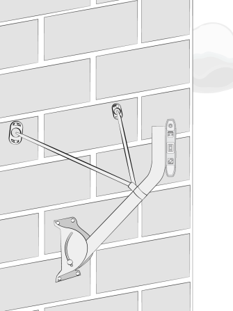
Attaching the Footplate
To begin installing a wall mount on a brick or poured concrete wall, locate a brick that is at least 30 inches from:
- The edge of a door
- The edge of a window
- The building corner
- The top of the wall
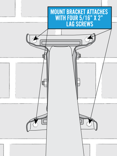
Center the footplate so that the screw holes are not in the mount.
Mark the top-left outside corner hole for the first ½ inch pre-drilled hole.
Hold the footplate in the center of the brick and mark the top-left outside corner hole. Remove the footplate and use a concrete drill bit to drill a ½ inch hole on the mark.
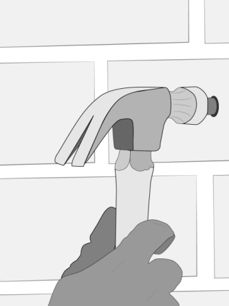
After pre-drilling, hammer the double expansion anchor into the hole, ribbed end in first, until it is flush with the surface of the base material.
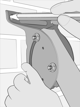
Place the footplate on the wall, aligning the top-left outside hole with the hole in the wall. Add a silicone-based sealant, and then secure with a 5/16 x 2 inch flanged lag screw
Leave this top-left outside screw loose enough to level the footplate.
Hold the level along the side flange or the top of the footplate, and slide the footplate side to side until the horizontal bubble is centered. When the footplate is level, mark the wall in the remaining three outside holes of the footplate. The center holes are not used because they will likely align over the mortar. Pre-drill the outside holes of the footplate as before.
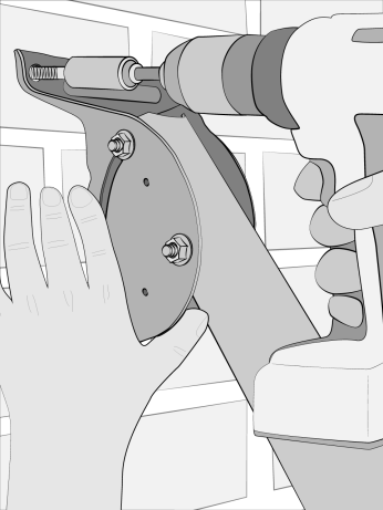
Use a hammer to insert one expansion anchor into each hole. To secure the other three corners, use 5/16 x 2 inch flanged lag screws
Confirm that the footplate is level, and finish tightening all lag screws, which firmly secures the footplate to the wall.
Adjusting the Mast Tube
Loosen the 5/16 X ¾ inch carriage bolt that is in the footplate’s arched slots and the mast tube
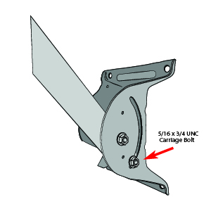
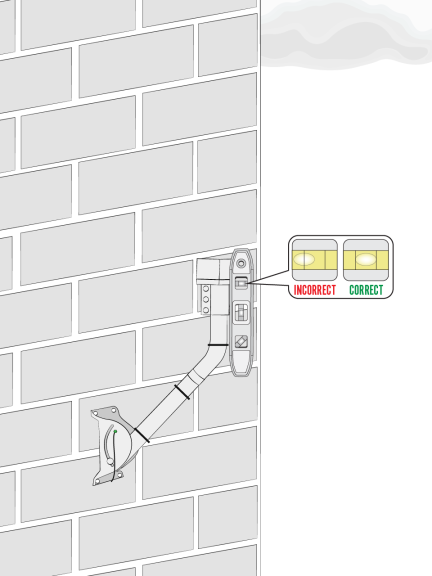
Swing the mast tube up and use a level to level the mast tube. Tighten the footplate carriage bolts to ensure the mast is plumb. Complete final mast tube leveling after installing the monopoles.
Adding the Monopoles
The installation kit provides the adjustable monopoles that are required on wall and sloped roof mounts. These are the only Viasat-approved monopoles; do not use others.
Loosen all of the 5/16 inch joint hardware.
Caution! Edges may be sharp; gloves are recommended.
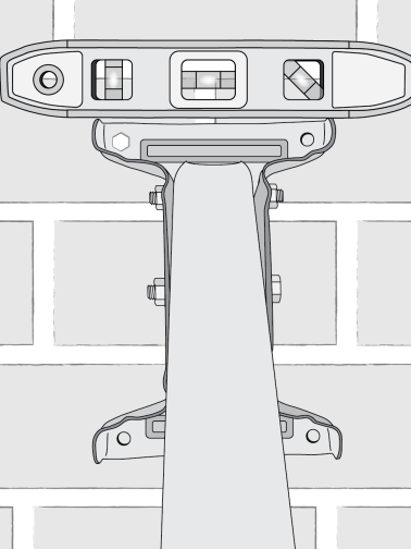
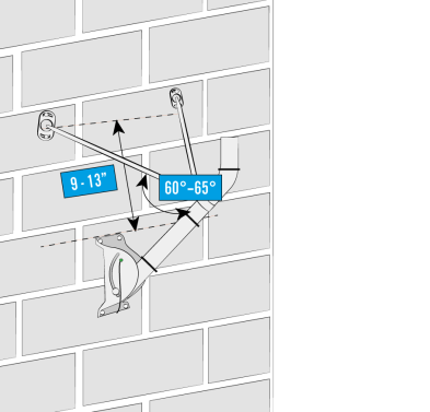
Slide each collar over the top of the mast tube, and down below the bend. Make sure the top collar/sleeve is 2 inches below the bend. Point the collar flanges towards the mount surface.
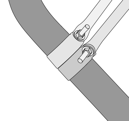
Position the monopoles 9 to 13 inches from the top edge of the footplate, which should put the monopoles at an angle of 60° to 65° from the tube as shown.
Lag shields must not be placed in mortar joints!
Using the same technique and process as the footplate, attach the foot of each adjustable monopole to the wall using 2, 5/16 X 3 inch lag screws per foot.
Install the monopoles on opposite sides of the mast tube.
Remember to add silicone sealant to the holes before adding the lag screws.
Tighten all the 5/16 inch hardware joints.
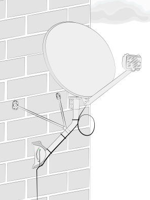
Once the mast tube is level, you are ready to attach the antenna.
Complete final mast tube leveling after installing monopoles and tighten all mount nuts and screws.
Once the mast tube is level, perform a quick tug test on the mount to verify that it is stable. Then you are ready to attach the antenna.