VS1300 Assembly Job Aid
Summary
This Job Aid covers:
Verify AZ/EL Assembly Alignment
Boom Arm, Reflector, and TRIA Assembly
This Job Aid supports all Technician audiences. This job aid covers the VS1300 ODU antennas.
Verify AZ/EL Assembly Alignment
Aligning the Azimuth
The AZ/EL assembly consists of the Tube Canister, Azimuth Plate, Azimuth Base, and Elevation Bracket.
Loosen the bolts on the bottom of the AZ/EL assembly.
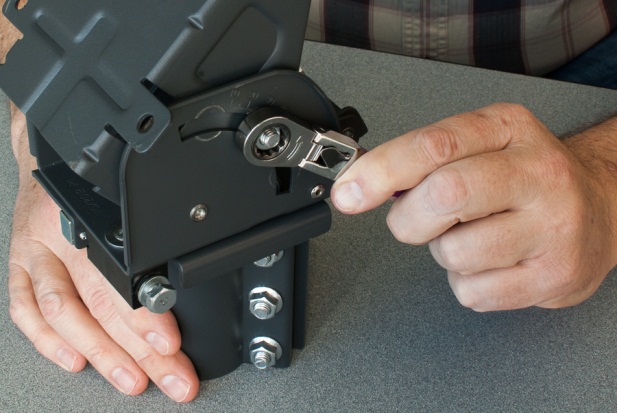
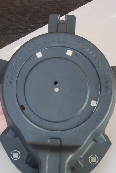
Turn the Fine Azimuth adjustment nut until the indicators on the base of the AZ/EL are at Zero (0).
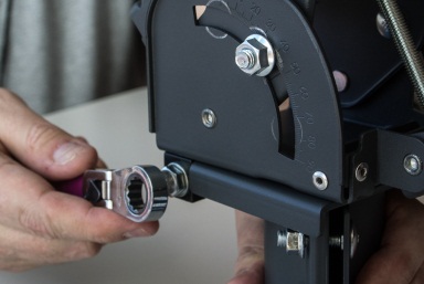
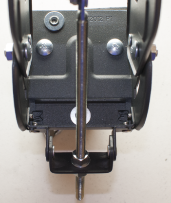
Once the azimuth is centered, retighten the bolts on the bottom of the AZ/EL assembly to secure the setting while the antenna is being built.
IMPORTANT: The alignment of the Fine Azimuth Adjustment assembly is critical. If the Fine Adjustment is misaligned, it may not be possible to adjust the Azimuth to the satellite.
Elevation Gauge Adjustment
The following information provides the steps used to set the antenna elevation prior to assembly.
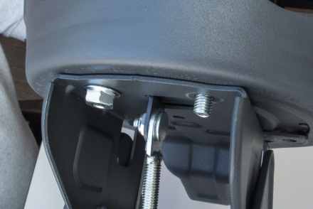
Pre-set the elevation as per the Work Order to the approximate value. Ensure the elevation lock down bolts are loosened, and then loosen the top nut on the elevation rod. Wind the nut up out of the way.
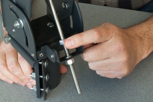
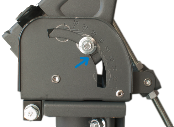
Manually adjust the elevation setting to the relevant position by turning the Elevation Adjustment Nut.
Note: The elevation is measured with the etched line just below the lock down bolt.
When the coarse elevation adjustment is complete, wind the top nut down the elevation rod until it bottoms out on the cast pivot bracket. Tighten the elevation lock down bolts on the AZ/EL assembly. This will secure the setting while the antenna is being built.
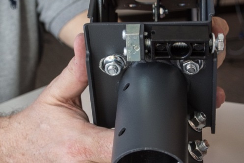
Antenna Back Bracket Assembly
The following information provides the steps used to build the Antenna Back Bracket Assembly.
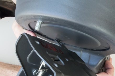
Construct the Back Adjustment Assembly by fastening the Skew Plate to the front of the Elevation Bracket, through the Antenna Back Bracket. Align the holes that are closer-set to the top of the Antenna Back Bracket. Pass four Carriage Bolts through the skew plate, then the Antenna Back Bracket, and finally through the front of the Elevation Bracket.
Set the skew to the setting provided on the work order.
Secure the Skew Plate using a flanged nut on each Carriage Bolt.

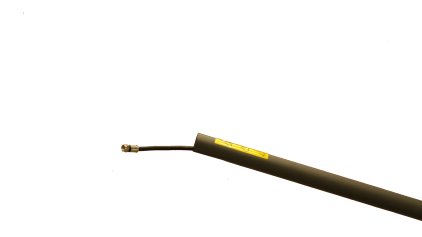
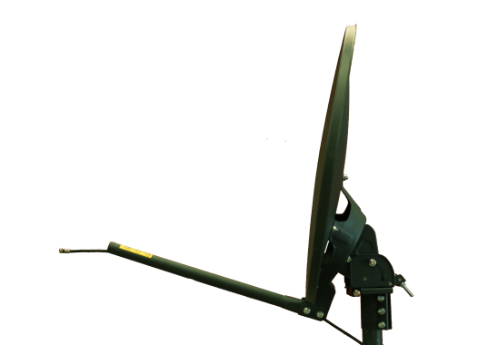
Boom Arm, Reflector, and TRIA Assembly
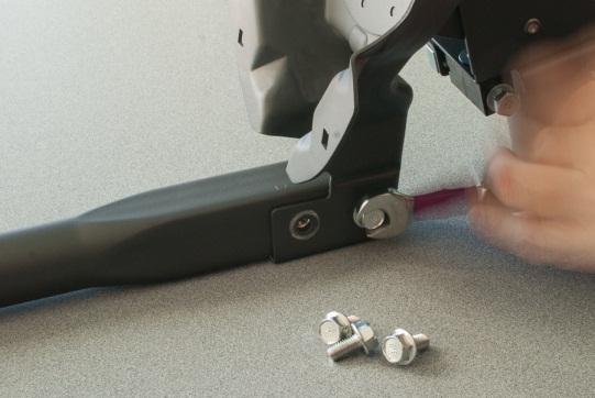
Attach the Boom Arm Assembly:
Slide the Boom Arm into the slots on the Back Bracket. Secure the Boom Arms to the back bracket with four hex head bolts. Tighten the bolts to secure the assembly.
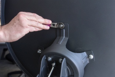
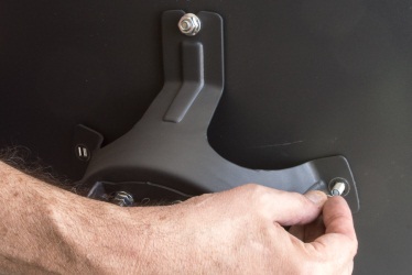
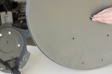
Attach the Reflector:
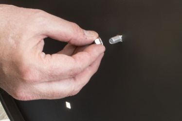
First, pass a carriage bolt through the top position on the reflector and attach a flange nut. Do not tighten the nut all the way. Slide the carriage bolt into the slotted tab on the top of the back bracket. This will hold the reflector in place while the other four carriage bolts are installed. Tighten the five bolts to secure the reflector to the back bracket.
After mount installation is complete, place the antenna on the mast.
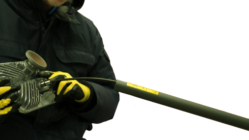
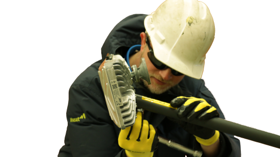
Attach the TRIA:
The COAX cable run must be completed before attaching the TRIA to the Boom Arm. Feed the cable through the Boom Arm and secure the cable to the TRIA. Secure the TRIA with two bolts.