Stub Mount Job Aid
Surfaces
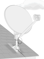
The only approved surface for a low-profile “stub” mount* is a sloped roof:
- Made of asphalt shingles
- Not damaged or decayed
- With no more than 3 layers of shingles
Note: Use the low-profile (stub) mount with a non-penetrating mount for flat roofs.
Structural Elements
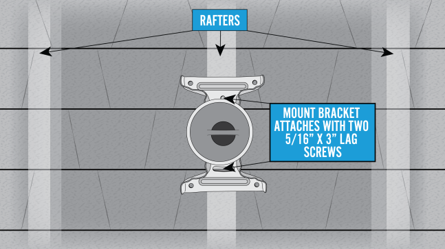
The approved structural elements for a low profile sloped roof mount are: rafters or trusses.
- What must be secured in the structural elements?
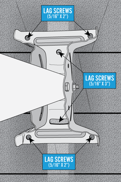
- The 2 center 5/16 X 3 inch lag screws in the footplate
- What must be secured in the roof?
- The outside corner flanged lag screws
Important considerations
DANGER! Locate power lines before you start the installation. These include overhead and underground power lines, electric lights, and power circuits.
Other Considerations
- The ground block must be within 20 feet of the NEC approved ground
- The total cable run from the modem to the TRIA must be less than 150 feet
- All antennas must be located at least 20 feet from any overhead power lines and 3 feet from any standard power circuit or electric light
- Position the mount so that the bottom of the reflector is at least 4′ above any walking surface
Mounting Materials for Footplate
The Technician must provide the following materials:
- Tar-based sealant (Bishop Tape preferred)
Attaching the Footplate
The footplate is the centerpiece of the mount, so correctly attaching it to the surface is critically important.
Locate the structural elements (rafters) that will place the footplate in position to meet all of the appropriate considerations listed above.
Note: Use a deep-scan stud finder to locate the rafter/structural elements.
Hold the footplate in the center of the rafter and mark the top center hole. Remove the footplate and predrill 1/8 inch hole on the mark.
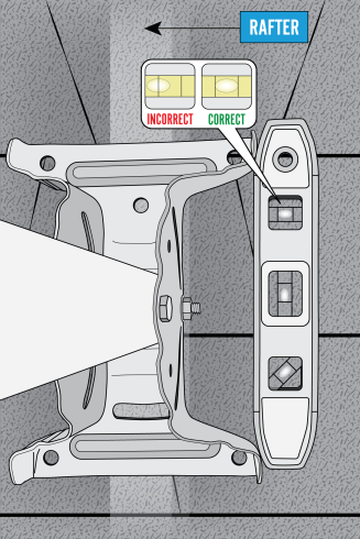
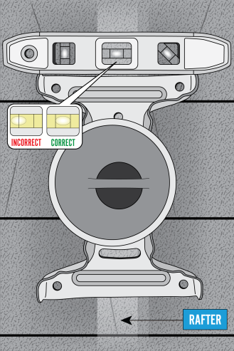
Use a level to verify that the center line of the footplate, defined by the footplate’s center holes, is level.
Mark and predrill the bottom center hole.
Mark and predrill the remaining four 1/8 inch holes; one in each outside corner.
Cover the bottom of the entire footplate with tar-based sealant.
Secure 5/16 X 3 inch lag screws through the top and bottom center hole of the footplate and the rafter. Leave these loose enough to level the footplate.
Correctly align the footplate over the 1/8 inch holes. This will allow correct placement directly over rafters or trusses.
Install a 5/16 X 2 inch flanged lag screw in each of the outside corners.
Securely tighten all the screws.
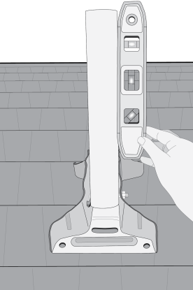
Adjusting the Mast Tube
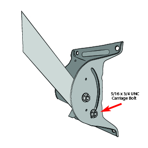
Loosen the 5/16 X ¾ inch carriage bolt that is in the footplate’s arched slots and the mast tube.
Swing the mount tube up and use a level to level the mount tube. Tighten the footplate carriage bolts to ensure the mount is plumb. Complete final mount tube leveling after installing the monopoles.
Once the mast tube is level, perform a quick tug test on the mount to verify that it is stable. Then you are ready to attach the antenna.