Telescoping Pole Mount Job Aid
Release Date: May 2018
 Summary
This Job Aid covers:
Structural Elements Important Considerations Other Considerations
Other Installation Resources Installing a Telescoping Pole Mount
This Job Aid supports the Global Business Services technican audience.
Surfaces
The only approved location for a telescoping pole mount is in firm ground, with no
danger from flooding. Telescoping pole mounts are for Community Wi-Fi and not residential applications.
Structural Elements
None
Important Considerations
- The Telescoping Pole Mount installation requires additional materials not provided with the equipment
- This installation type may also require building permits. Technicians are required to check the local building codes.
- At minimum, the following requirements must be met for the telescoping pole mount:
- Pole extends at least 12 inches below the ground surface, and is set in concrete
- When fully extended, pole must be placed a minimum height of 15 above the ground
Other Considerations
- The ground block must be within 10 feet of the NEC approved ground source
- All antennas must be located at least 20 feet from any overhead power lines and 3 feet from any standard power circuit or electric light
DANGER! Always call your local safe dig number to locate power lines before you start the installation. These include overhead and underground power lines, electric lights, and power circuits.
Other Installation Resources
For complete assembly/installation instructions, please see manufacturers’ guides: Ruckus Zoneflex T300 Outdoor AP (US)
SXT Lite5 ac
Note: Ethernet cable used must be on the Viasat Approved Materials List job aid
Installing a Telescoping Pole Mount
- Dig the hole 8 inches in diameter (to fit the concrete form tube) and two feet deep, with straight sides
Ensure that hole is no greater than 10 feet from power source/pedestal
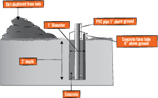
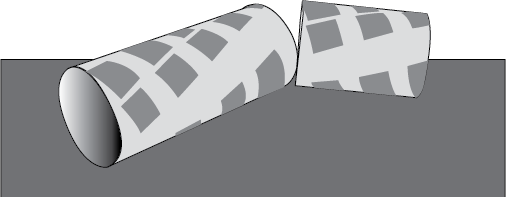
2. Concrete form tubes with a 8 inch inside diameter come in standard 4 foot sections
Cut concrete form tube down to 3 feet
Drill a 1 inch diameter hole at 12 inches from either side of the cut concrete form tube
3. Place the 3 foot concrete form tube in the hole with 1 inch hole toward bottom. Tube will extend 12 inches above ground level
Re-pack dirt around the outside of the concrete form tube, so that any gaps between the form tube and the ground are filled, and the form tube is level, stable, and secure
4. Dig a 1 foot deep trench from form tube to power location “ensure cable locates completed”
Assemble 2 PVC pipe conduit sections as depicted
Insert 1 PVC pipe conduit section with straight shorter end protruding from form tube hole
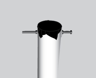
5. Remove black plastic sleeve from pole box, place duct tape over one sleeve end, drill hole 2 inches from bottom for ¼ inch x 6 inch bolt/anti-spin device
Insert ¼ inch x 6 inch bolt and secure ¼ inch nut and corresponding washer on each side
Tighten nuts until the anti-spin device is centered through the PVC pipe
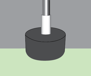
6.Place 3 foot PVC pipe in center of concrete form tube
It will extend 18 inches above ground level (6 inches above the top of the form tube)
7. Secure black plastic sleeve and 1 PVC pipe conduit section by pouring at least 150 pounds of quick-setting concrete into the concrete form tube
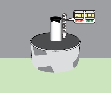
8. Level black plastic sleeve while the concrete dries
Note: The black plastic sleeve must be completely level in order for the pole mount to be successful
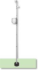
9. Lay the telescoping pole along the ground and extend to height between 15 to 20 feet
Ensure that each section of the pole is firmly locked in place and does not spin or collapse back down
Note: Only the bottom section will be drilled for the anti-spin device
Mount the remote AP 3 to 6 inches from the top of the pole
Mount the remote SXT 2 to 4 feet from the top of the pole (ensure SXT will have line of sight to omnidirectional/sector antenna)
Note: Install the SXT oriented so that the CAT5 cable enters from the bottom
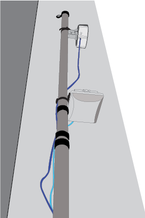
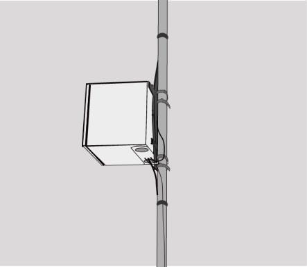
10. Mount the weatherproof (NEMA rated) enclosure a minimum of 7 feet above ground level, with 2 self-tapping screws
Use 2 U bolts. 1 on the top and 1 at the bottom
Unscrew right and left gland caps and glands, connect Ethernet cabling through holes, feed glands onto cables and reinsert glands
Screw gland caps back on.
Connect protruding Ethernet cables to SXT and AP.
Secure Ethernet cables to telescoping pole using cable ties & coil excess Ethernet cables and secure drip loop/s to pole.
11. Once the concrete is hard set:
- Cut away the concrete form tube to ground level
- Insert telescoping pole into black plastic sleeve until it is secure against the anti-spin device at the bottom of the sleeve
12. Ensure that the SXT faces the direction of the Base Station, for point-to-point signal
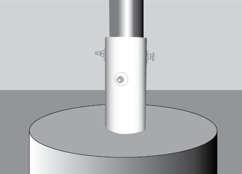
13. Mark black sleeve for 2 anti-spin devices:
- At 90 degree angles from each other
- One 2 inches from top of the sleeve
- One 3 inches from top of the sleeve
Drill through both sides of sleeve and telescoping pole for ¼ inch x 6 inch bolts
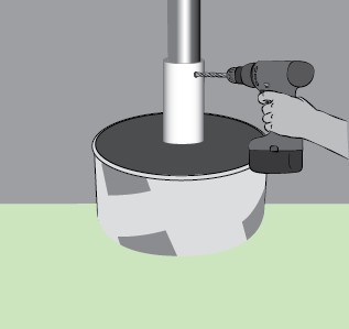
14.Place ¼ inch x 6 inch bolts, washers, and nuts through holes Tighten ¼ inch nuts until telescoping pole is secure
15. Run power cable through conduit and into 1 foot trench
Run power cable along trench and through second PVC pipe conduit section, plug into local power, and fill trench.