Using an Inclinometer
Summary
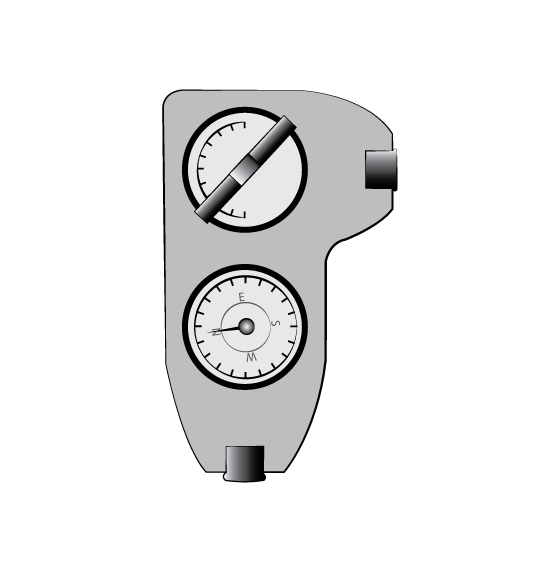
The inclinometer is an essential tool in the field which has been used for many years. There are many options for inclinometers available to use, but we will learn how to use the dual inclinometer with this step by step document.
This Job Aid covers:
This Job Aid supports the Technician audience.
Finding Azimuth
Remove the inclinometer from its pouch
Make sure the Lanyard is attached
Important: Ensure the inclinometer is not near any heavy metal such as the reflector or electrical components. Allow at least 3 feet for clearance to avoid any interference.
Once the location has been determined, hold inclinometer in the palm of your hand and lay it flat or horizontal to determine the azimuth location of the satellite.
Note: Check the Inclinometer and verify it is in working order. Excessive bubbles could impede the end results.
Place the Inclinometer flat with the gauges facing up, then hold steady and place it to your dominant eye.
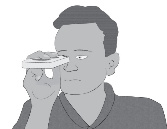
With both eyes open, look into the eye glass viewer
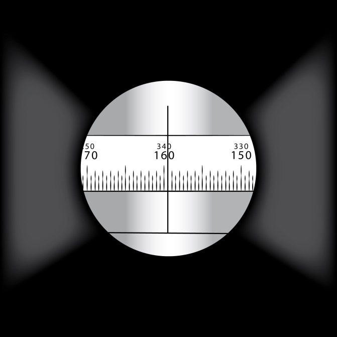
A marker will display with the Azimuth readings
While standing in place, shift your position east or west depending on location to locate the azimuth degrees found on the work order
While continuing to have both eyes open, an impression of the gridline appears and the user should be able to determine a landmark to hold your position.
This will give you a rough estimate of the location of the satellite position in the sky.
Finding Elevation
While standing in the same position to find the azimuth location, continue to find the elevation location.
- Turn the inclinometer to the upward position with the glass viewer towards you.
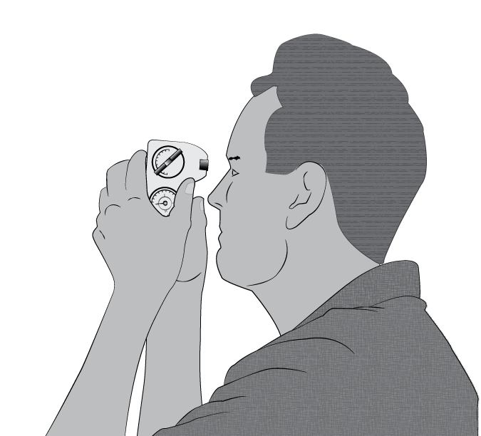
With both eyes open, using your dominant eye, look into the viewer and locate the number scale inside
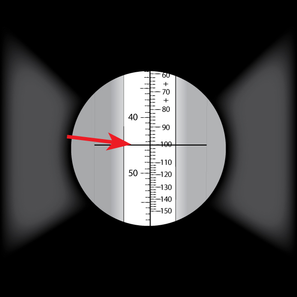 Important! There are 2 sets of numbers; use the numbers on the left side.
Begin tilting your head in an upward motion while looking into the viewer until you can identify the degree marked 45.
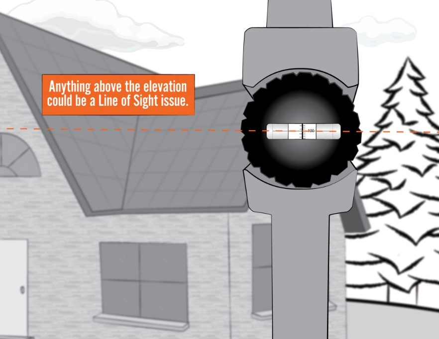
Continuing to keep both eyes open, an illusion of the gridline will appear and a line will display in front of the landmark you have chosen.
Remember to make sure that there is nothing above the line displayed.
-
- If there are no objects above the line; this is an indication there is no LOS issue.
If there is an object above the line; this is an indication that there is a LOS issue.
Once you have determined that the LOS is clear, begin installing the antenna