Panel/Lap Siding Wall Mount Job Aid


Surfaces
Approved surfaces for a wall mount are walls made of panel or lap siding.*
*Other approved surfaces covered in separate job aids.
Structural Elements
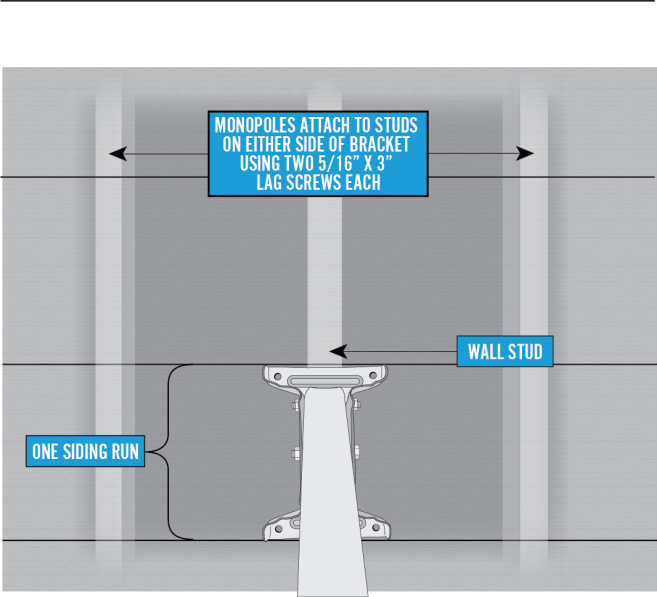
The approved structural elements for a wall mount in panel or lap siding are wall studs.
What must be secured in the structural elements?
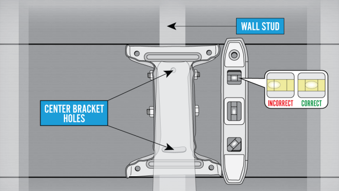
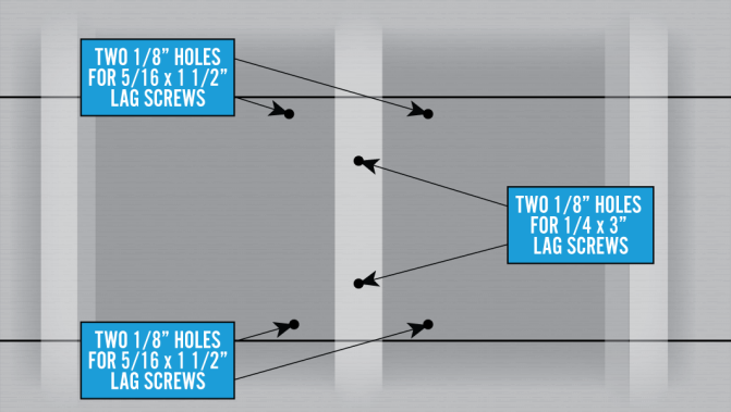
- The 2 center 5/16 X 3 inch lag screws in the footplate, and
- The 2, 5/16 X 3 inch lag screws in the adjustable monopoles
Important considerations
DANGER! Locate power lines before you start the installation. These include overhead and underground power lines, electric lights, and power circuits.
- The center foot plate must be installed at a stud that allows for proper monopole orientation. Monopoles:
- Must be installed to studs
- Cannot be attached to window casements and/or door frames
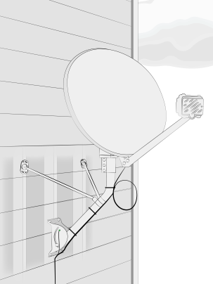
- Position the mount so that:
- The building eave or overhang will not block or partially shadow the line of site
- The bottom of the reflector is at least 4′ above any walking surface
Other Considerations
- The ground block must be within 20 feet of the NEC approved ground
- The total cable run from the modem to the TRIA must be less than 150 feet
- All antennas must be located at least 20 feet from any overhead power lines and 3 feet from any standard power circuit or electric light
Mounting Materials for Footplate and Monopoles
The Technician must provide the following materials:
- Silicone sealant
Attaching the Footplate
The footplate is the centerpiece of the mount, so correctly attaching it to the surface is critically important.
To begin installing a wall mount on a panel or lap siding wall, locate an area where the center foot plate will be installed in a stud that allows for proper monopole orientation. Monopoles:
- Must be installed to studs
- Cannot be attached to window casements and/or door frames
Locate the structural elements (studs) that will place the footplate in position to meet all of the appropriate considerations listed above.
Note: Use a deep-scan stud finder to locate the stud/structural elements.
Hold the footplate in the center of the stud and mark the top-center hole. Remove the footplate and drill a 1/8 inch hole on the mark.
Using one 3 inch lag screw, secure the footplate to the wall through the top-center hole. Leave it loose enough to level it.
Use a level to verify that the center line of the footplate, defined by the footplate’s center holes, is level. Use a pencil or marker to mark the bottom-center hole and the four outside corner holes of the footplate.
Note: Do not over tighten the lags. This could cause the holes to become stripped, resulting in the mount not being secure.
After removing the footplate, use these marks to drill the remaining five 1/8 inch holes; one in the center bottom and one in each outside corner.
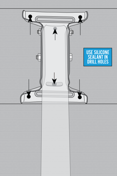
Fill each hole with silicone sealant.
Reposition the footplate over the holes.
Install two 5/16 X 3 inch lag screws in the center holes.
Install a 5/16 X 2 inch lag screw in each of the outside corners.
Verify that the footplate is level and securely tighten all the screws.
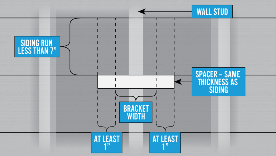
Adjustment for Narrow Siding
When lap siding is less than seven inches, the footplate will span more than one siding run. Support the overlapping portion of the footplate with a wood or plastic spacer that is the same thickness as the siding. The spacer should extend at least one inch on either side of the footplate. Center the spacer over the stud and attach to the siding with screws. Then, pre-drill the spacer with 1/8 inch holes to accommodate the two lower corner lag screws.
Use the lap siding installation process outlined above, to install the footplate.
Adjusting the Mast Tube
Loosen the 5/16 X ¾ inch carriage bolt that is in the footplate’s arched slots and the mast tube
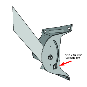
Swing the mast tube up and use a level to level the mast tube. Tighten the footplate carriage bolts to ensure the mount is plumb. Complete final mast tube leveling after installing the monopoles.
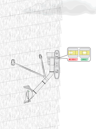
Adding the Monopoles
The installation kit provides the adjustable monopoles that are required on wall mounts. These are the only Viasat-approved monopoles; do not use others.
Loosen all of the 5/16 inch joint hardware.
Caution! Edges may be sharp; gloves are recommended.
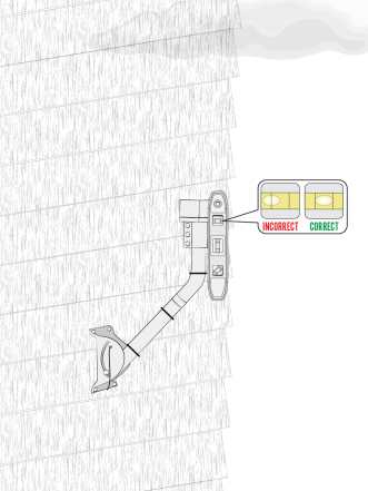
Slide each collar over the top of the mast tube, and down below the bend. Make sure the top collar/sleeve is 2 inches below the bend. Point the collar flanges towards the mount surface.
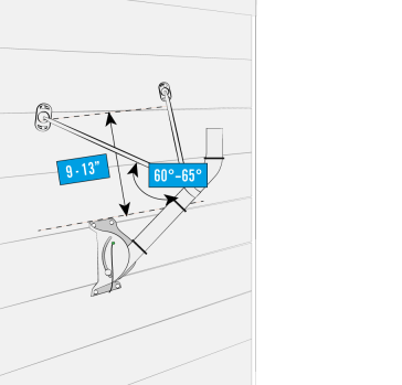
Position the monopoles 9 to 13 inches from the top edge of the footplate to the 2 adjacent wall studs, which should put the monopoles at an angle of 60° to 65° from the tube as shown.
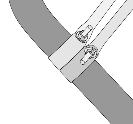
Using the same technique and process as the footplate, attach the foot of each adjustable monopole to the structural element (stud) using 2, 5/16 X 3 inch lag screws per foot.
Install the monopoles on opposite sides of the mast tube.
Remember to add silicone sealant to the holes before adding the lag screws.
Tighten all the 5/16 inch hardware joints.
Complete final mast tube leveling after installing monopoles and tighten all mount nuts and screws.
Once the mast tube is level, perform a quick tug test on the mount to verify that it is stable. Then you are ready to attach the antenna.