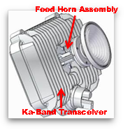
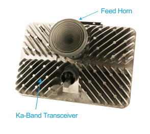
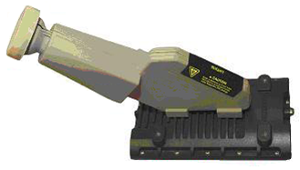
The Transmit Receive Integrated Assembly (TRIA) consists of two main components. The Feed Horn Assembly is responsible for directing the Transmit signal or capturing the Receive signal. This assembly has two components:
Polarized Feed Horn
Ortho-Mode Transducer
The Transceiver converts the signal frequency between the satellite signal and the modem.
VS1300 pTRIA
VS1300 eTRIA
VS1100/VS1200 TRIA
Anik F2 Covered TRIA
WildBlue 1 and AMC 15 Covered TRIA
Feed Horn Assembly Models
The Feed Horn Assembly directs, separates, and filters the satellite Radio Frequency to and from the satellite. Each component supports the following essential functions:
There are various types of Feed Horn Assembly models and each is configured at the manufacturer and is not designed for field modification. The Feed Horn polarization position determines which satellite the TRIA communicates with.
Weather Protection Cover Feed Horn Assembly:
VS1300 pTRIA
VS1300 TRIA
VS1100/VS1200 TRIA
Anik F2 Covered TRIA
The covered Feed Horns are available in the left Polarization. It is not necessary to remove the cover to determine the Polarization information. It is easily viewable from the outside.
WildBlue 1 and AMC 15 Covered TRIA
The covered Feed Horns are available in the right Polarization. It is not necessary to remove the cover to determine the Polarization information. It is easily viewable from the outside.
The VS 1100/VS1200 TRIA and VS1300 eTRIA are sealed units and do not require a weather cover.
TRIA Handling
It is important to handle electronic equipment with care to avoid damaging delicate components. The TRIA is such a component. Keep the TRIA in the shipping box for transport to the installation site. Place the boxed TRIA in a place where it will not be dropped, shaken, or experience sudden jolts.
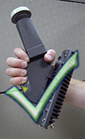
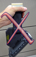
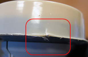
Once at the installation site proper handling of the TRIA is required. Commonly, technicians grasp the TRIA around the base of the feed horn. Grasping the TRIA by the plastic cap applies damaging stresses to the plastic cap and may cause the seal to break and/or tear when the “lip” at the base of the cap is caught by gripping the TRIA in this way.
Proper TRIA Handling
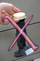
Improper TRIA Handling
Maintaining the integrity of the cap and the glue seal is critical to preventing TRIA water damage. Avoid contact with the feed cap, especially the lip as the feed cap is not designed as a lifting point for the TRIA assembly.
Carrying a TRIA up a ladder
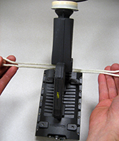
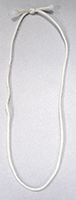
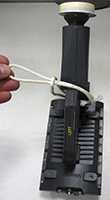
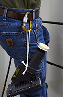
It may be cumbersome to carry a TRIA up a ladder. Commonly the TRIA is held in one hand, leaving the other hand available to hold on to the ladder. A better way to carry the TRIA is with a sling. Construct a secure sling from a 30-inch section of rope or twine, tied into a loop. Wrap the sling around the base of the polarizer. Attach the sling to a belt clip or tool belt, leaving both hands free to climb the ladder. This is a secure position for holding the TRIA, and keeps the feed cap elevated to reduce risk of damage. Avoid dropping or banging the component as this may damage internal components.
Construct a sling with rope or twine, and loop the sling at base of polarizer
Pull loop snug around the base
Grasp the sling and attach to belt or tool belt
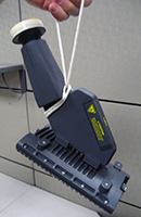
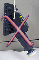
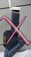
The following sling positions are not recommended because the Feed cap is vulnerable to damage.
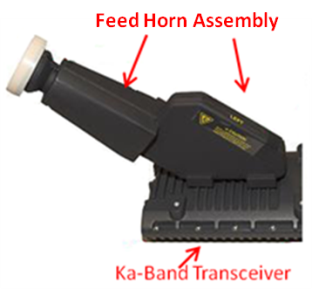
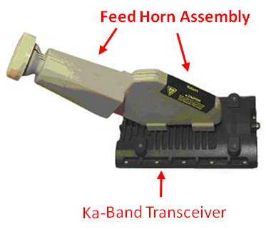
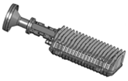
Transceiver Model VS1300 eTRIA
The eTRIA, which comes in 3W and 6W versions has the following features:
Smaller, more compact design
No bracket is required – the eTRIA attaches directly to the shortened, narrower boom arm
Lighter weight – the VS1100/1200 TRIA weighed nearly 7 lbs whereas the eTRIA weighs less than 3.5 lbs
Single COAX cable is connected through the boom arm, not on the outside using ties as with previous models for easier installation
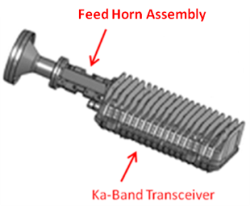
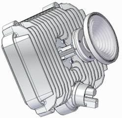
Transceiver Model VS1100/VS1200
The VS 1100 Transceiver thas some unique enhanced features and comes in two models: 2 IFL and 1 IFL.
The VS1100 2 IFL TRIA has these features:
Completely sealed – no weather cover required
Feed Horn and Ka-Band Transceiver are in line with one another
Operates with SurfBeam 2 Modem Single COAX connector
Terminator is required
The combined Transmit (TX)/ Receive (RX) connector is located on the front, right of the TRIA
The used Receive (RX) connector is located on the front left of the TRIA and is covered with an Technician provided Terminator
Ground Screw connector is located on the front of the TRIA just right of the Feed Horn
The VS1100 1 IFL TRIA has these features:
Completely sealed – no weather cover required
Feed Horn and Ka-Band Transceiver are in line with one another
Operates with SurfBeam 2 Modem Single COAX connector
The combined Transmit (TX)/ Receive (RX) connector is located on the front, right of the TRIA
Ground Screw connector is located on the front of the TRIA just right of the Feed Horn
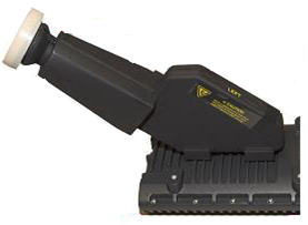
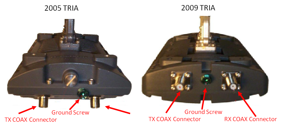
Transceiver Models 2005 and 2009
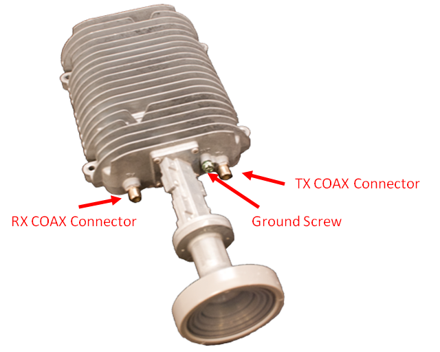
The Transceiver connects to the Satellite Modem through the COAX cable and provides the following functions:
Transmit: Converts frequencies from the Satellite Modem and directs it to the TRIA. When viewed from behind the TRIA the transmit connector is on the left side.
Receive: Converts the signal from the Feed Horn Assembly then amplifies the signal and directs it to the Receive port. When viewed from behind the TRIA the Receive connector is on the right side.