SurfBeam 2 Point and Peak Job Aid


Summary
This Job Aid covers:
This Job Aid supports all technician audiences.
This Job Aid supports all SurfBeam 2 User Terminals: VS1100, VS1101, VS1200, and VS1300.
Note: Images for the VS1100 appear on the left; images for the VS1200/VS1300 appear on the right.
Enter Installation Mode
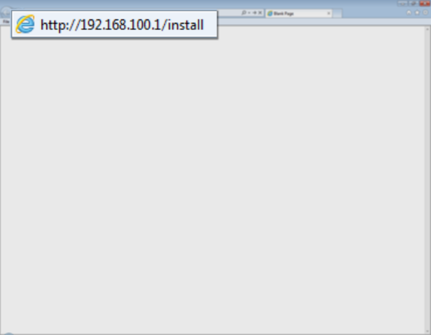
Open the computer’s Internet browser and type this URL into the Address bar:
http://192.168.100.1/install
Click the forward arrow in the Address bar. The modem enters the Installation Mode.
Note 2: If a “Website Not Found” error appears, click the browser’s refresh button until the page appears
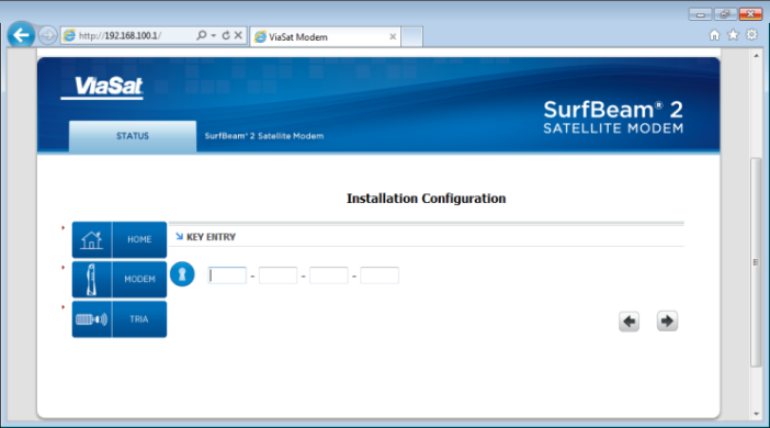
Find the 16-digit Modem Key on the work order, and type it into the fields.
Click the large forward arrow in the lower right corner of the screen.
Important: Do not press Enter, as this makes the modem leave the Installation mode.
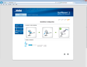
The Installation Configuration page changes.
Confirm that these two events are happening:
- The SB2 modem’s RX and LAN lights are flashing.
- The TRIA is emitting the ‘heartbeat’ tone
The SB2 and TRIA are ready for the Point and Peak process.
Point Azimuth
Point the antenna to the course azimuth.
SB2 TRIA tone sequence
Recall that the SB2 modem must learn about its frequency set. This happens when the technician sweeps the antenna from each side of the azimuth or the elevation.
| Inside the Frequency Set the TRIA emits … | Outside the Frequency Set the TRIA emits … |
|
|---|---|---|
| During Point Azimuth | Ring ring, low/slow, high/fast, high/steady | Heartbeat |
| During Peak Azimuth/Elevation | Low/slow, high/fast, high/steady | None – always inside the frequency set |
Tone Frequencies
For those who use hearing aids, or other audio augmenting devices, the frequencies for the tones are as follows:
Heartbeat: 3KHz
Pointing Tones: 2.5 – 3.1KHz
Peaking Tones: 2.5, 2.95,3.1 and 3.3KHz
Follow these steps to point the Azimuth of the antenna.
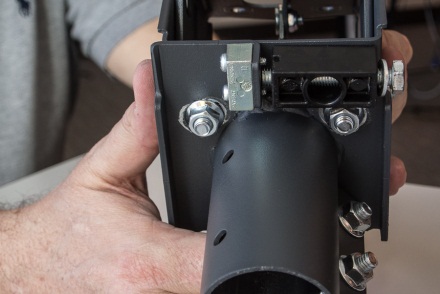
Sweep the antenna from side to side, checking the tightness of the three flange nuts on the mount canister. The antenna should move, but not too easily. Tighten or loosen the flange nuts as needed.
Note: After placing the antenna on the mount tube, align it to the Azimuth setting indicated on the word order.
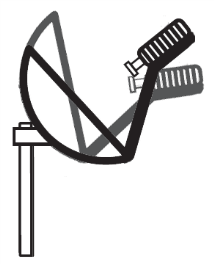
Sweep the antenna to the right, about 10 degrees away from the line-of-sight selected during the Site Survey.
Sweep the antenna toward the left, listening for the TRIA to emit the ‘ring ring’ tone. Continue sweeping the antenna toward the left until the TRIA emits the ‘heartbeat’ tone. Stop, as this is the end of the first learning pass.
Note: Disregard any ‘beep bop’ tones. The TRIA does not recognize these satellites.

![]()

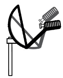
Reverse the direction of the sweep, and listen for the TRIA to progress through the tone sequence. Stop the sweep when the TRIA emits the heartbeat tone. This is the end of the second learning pass.
Note: Use a slow, consistent tension on the antenna during this sweep. Not all of the tones may be heard.

![]()

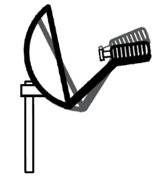
Reverse the direction of the sweep again, now sweeping to the center, and listen for the TRIA to emit the high/steady tone. The antenna is now in the center of the beam.


![]()
Finish this step by tightening the Flange bolts, starting with the top to maintain an even pressure on the Tube canister.
Note: The high/steady tone may dip while tightening the Flange bolts. If the tone does not return to the high/steady, then repeat the step. Remember to reset the modem’s learning by sweeping the antenna away from the satellite, and holding the Inclinometer bracket over the feed horn.
Peak Azimuth
The following information reviews the steps to complete the peak (fine) antenna Azimuth adjustment. VS1100 images are on the left; VS1200 images are on the right.
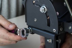
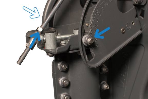
Loosen the Azimuth base plate bolts using a 13mm ratchet.
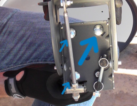
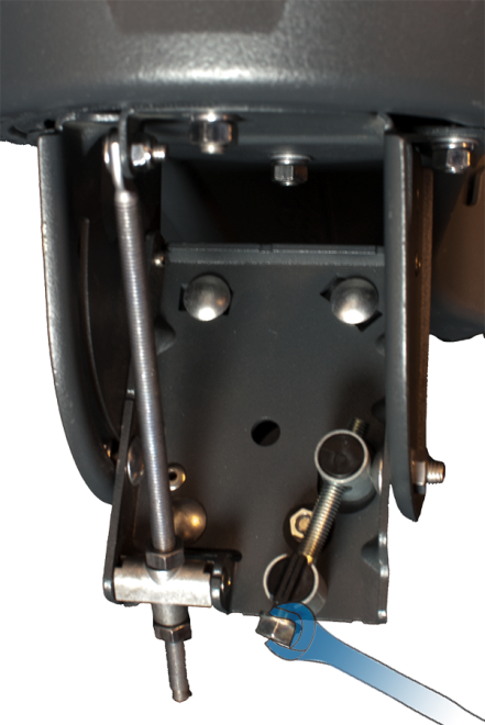
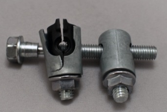
Using an open wrench, rotate the hex head of the Azimuth fine-adjust bolt.
Important: Do not pass the low/slow tone when peaking the antenna.
Rotating the hex head beyond the low/slow tone during the peaking procedure can compress the bolt’s attachments, causing them to fail.
Important: Avoid this problem by always centering the Azimuth fine-adjust bolt prior to pointing and peaking.
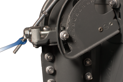
Sweep the antenna toward the left, listening for the TRIA to emit the low/slow tone, which means that the antenna has found the far edge of its frequency set. Stop, as this is the end of the first fine-tune learning pass.


![]()
Reverse the direction of the sweep, now sweeping to the right, and listen for the TRIA to progress through the tone sequence. Stop the sweep when the TRIA emits the low/slow tone. This is the end of the second fine-tune learning pass.
Note: Because this is a fine-tune pass, all tones should be present. Periodically pause and wait for the modem to evaluate the information coming from the antenna.

![]()

Reverse the direction of the sweep again, now sweeping to the center, and listen for the TRIA to emit the high/steady tone. The antenna is now in the center of the beam.


![]()
Finish this step by tightening the Azimuth base plate bolts.
Note: The high/steady tone may dip while tightening the base plate bolts. If the tone does not return to the high/steady, then restart the Point and Peak process. Remember to reset the modem’s learning by sweeping the antenna away from the satellite, holding the Inclinometer bracket over the feed horn, and then re-centering the Azimuth fine-adjust bolt.
Peak Elevation
The following information reviews the steps to complete the peak (fine) antenna Azimuth adjustment.
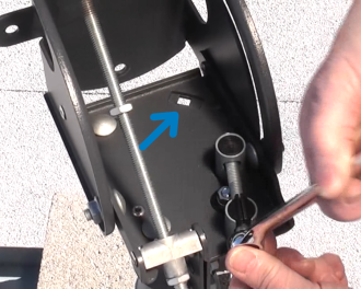
Slightly loosen the Lockdown Nuts in the Arched Slots on sides of the Elevation Bracket. Next, turn the top ½-inch Nut on the Elevation Rod away from the top of the Pivot Casting.
Use the open wrench on the lower Elevation rod nut.
Caution: Do not pass the low/slow tone when peaking the 75cm ODU.
Sweep the nut on the Elevation rod such that the TRIA drops ,and listen for the TRIA to emit the low/slow tone, which means that the antenna has found the far edge of its frequency set. Stop, as this is the end of the first fine-tune learning pass.
![]()

Reverse the direction of the sweep, now sweeping to raise the TRIA, and listen for the TRIA to progress through the tone sequence. Stop the sweep when the TRIA emits the low/slow tone. This is the end of the second fine-tune learning pass.
Note: Because this is a fine-tune pass, all tones should be present. Periodically pause and wait for the modem to evaluate the information coming from the antenna.
![]()

Reverse the direction of the sweep again, now sweeping to the center, and listen for the TRIA to emit the high/steady tone. The antenna is now in the center of the beam.
![]()

Finish this step by tightening the same bolts and nuts. Start with the top nut on the Elevation rod, and then the Elevation Lock Down bolts.
Note: The high/steady tone may dip while tightening the Elevation Lock Down bolts. If the tone does not return to the high/steady, then restart the Point and Peak process.
Important: Always completes two tests before obtaining Modem Lock: a Push/Pull test and a review of the RX SNR in the Signal Strength section of the Modem Browser Interface. Passing these tests prevents delays in Modem Lock and Provisioning because they confirm that the antenna has aligned correctly during Point and Peak.
Push/Pull Test
From behind the antenna, gently push and pull each side of the antenna.

Gently push and pull the top of the antenna
The test passes when the TRIA’s high/steady tone dips every time pressure is added to the antenna. The tone returns to its high/steady state when the pressure is removed.
If the tone rises, the alignment is not correct. Repeat the Point and Peak process. Remember to reset the modem’s learning by sweeping the antenna away from the satellite, holding the Inclinometer bracket over the feed horn, and then re-centering the Azimuth fine-adjust bolt.
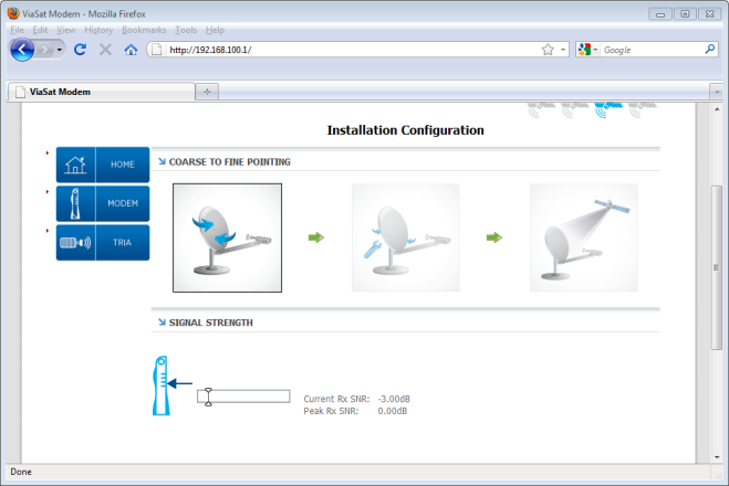
RX SNR in the Modem GUI
During the Point and Peak process, the modem Graphical User Interface records the current and the peak RX SNR levels in the Signal Strength section. These two levels will nearly match when an antenna is aligned correctly.
Levels showing differences of +/- 0.5dB are acceptable. Differences greater than 0.5dB should be seen as a failed Point and Peak. If levels are greater than +/- 0.5dB, repeat the Point and Peak process.
Remember to reset the modem’s learning by sweeping the antenna away from the satellite, holding the Inclinometer bracket over the feed horn, and then re-centering the Azimuth fine-adjust bolt.