Under-Eave Elephant Trunk Roof Mount Job Aid


Surfaces
The approved location for an “Elephant Trunk” under-eave mount is a building wall made of: wood, concrete, brick, or cinder block; and an eave with sloped or flat roof.
Structural Elements
The approved structural elements for an “Elephant Trunk” mount footplate are studs, rafters, trusses, concrete, brick, or cinder block.
Monopoles for this mount must be attached to the building fascia.
Important considerations
DANGER! Locate power lines before you start the installation. These include overhead and underground power lines, electric lights, and power circuits.
- The under-eave “Elephant Trunk” mount is one of the specialized mount types that require additional materials for installation, which may lead to additional time and materials costs for the customer
- Only use Viasat-approved under-eave mounts listed in the Viasat Approved Materials List job aid
Other Considerations
- The ground block must be within 20 feet of the NEC approved ground
- The total cable run from the modem to the TRIA must be less than 150 feet
- All antennas must be located at least 20 feet from any overhead power lines and 3 feet from any standard power circuit or electric light
- Position the mount so that the bottom of the reflector is at least 4′ above any walking surface
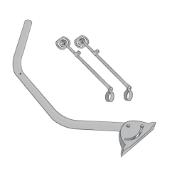
Mounting Materials for “Elephant Trunk” Mount
The Technician must provide the following materials:
- Technicians must review the mounting instructions provided with the mount, and provide any materials not included in the box
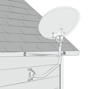
Installing an “Elephant Trunk” Under Eave Mount
Reminder: The “Elephant Trunk” mount is used with a sloped or flat surface.
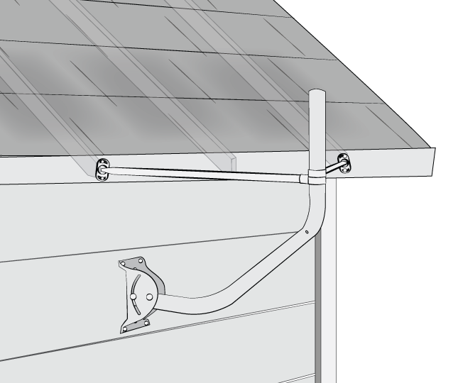
Attach the mount footplate to the structural element in the wall, and monopoles to the build fascia.
Always follow the manufacturer’s installation instructions, included with the mount.
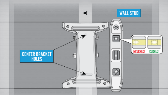
Locate the structural elements (studs, etc.) that will place the footplate in position to meet all of the appropriate considerations listed above. Do not forget to allow room for the adjustable monopoles.
Note: If wood, use a deep-scan stud finder to locate the stud/structural elements.
Note: If mounting to concrete, brick, or cinder block, follow mounting procedures in those job aids.
Hold the footplate in the center of the structural element (stud) and mark the top and bottom center holes. Remove the footplate and predrill 1/8 inch holes on the two marks.
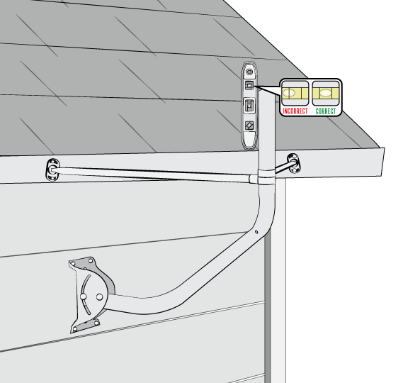
Use a level to verify that the center line of the footplate, defined by the footplate’s center holes, is level.
Mark and predrill the remaining four 1/8 inch holes; one in each outside corner.
Fill each hole with silicone sealant.
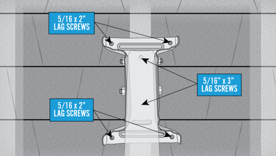
Secure 5/16 X 3 inch lag screws through the top and bottom center hole of the footplate and the rafter. Leave these loose enough to level the footplate.
Correctly align the footplate over the 1/8 inch holes. This will allow correct placement directly over the structural element.
Install a 5/16 X 2 inch flanged lag screw in each of the outside corners.
Verify that the footplate is level and securely tighten all the screws.
Adjusting the Mast Tube
Loosen the 5/16 X ¾ inch carriage bolt that is in the footplate’s arched slots and the mast tube
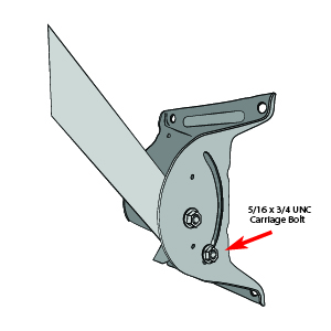
Swing the mast tube up and use a level to level the mast tube. Tighten the footplate carriage bolts to ensure the mast is plumb. Complete final mast tube leveling after installing the monopoles.
Adding the Monopoles
The installation kit provides the adjustable monopoles that are required on all mounts and sloped roof mounts, except the low profile “stub” mount. These are the only Viasat-approved monopoles; do not use others.
Loosen all of the 5/16 inch joint hardware.
Caution! Edges may be sharp; gloves are recommended.
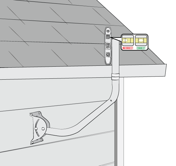
Slide each collar over the top of the mast tube, and attach 2 inches above the bend. Point the collar flanges towards the mount surface.
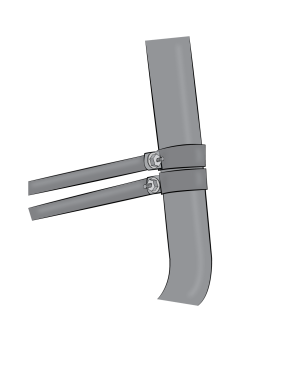
Using the same technique and process as the footplate, attach the foot of each adjustable monopole to the structural element (fascia) using 2, 5/16 X 3 inch lag screws per foot.
Install the monopoles on opposite sides of the mast tube.
Remember to add silicon-based sealant to the holes before adding the lag screws.

Tighten all the 5/16 inch hardware joints.
Complete final mast tube leveling after installing monopoles and tighten all mount nuts and screws.
Once the mast tube is level, you are ready to attach the antenna.